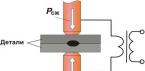
Basic technical data The radio control system allows you to remotely control the toy at a distance of up to 10 meters.
The operating frequency of the transmitter is 27.12 MHz.
The transmitter power is within 4-10 mW.
The current consumption of the transmitter is not more than 20 mA.
The weight of the transmitter with antenna and power supply is not more than 150 g.
The sensitivity of the receiver in the operating frequency band is not worse than 100 μV.
The current consumption of the receiver is not more than 20 mA.
The weight of the receiver is not more than 70 g.
The command device provides the execution of four different commands, which are repeated periodically.
The weight of the command device is not more than 70 g.
The receiver and transmitter are powered by Krona-VTs batteries. Principle of operation The transmitter consists of a modulator and a high frequency generator (Fig. 1). The transmitter modulator is a symmetrical multivibrator assembled on low-frequency transistors VT2 and VT3 of the MP40 type.
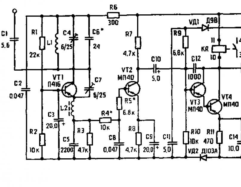
Fig.1 The high-frequency generator is assembled on a transistor VT1 type P416 according to a capacitive feedback circuit. When the VT2 modulator transistor is open, the generator circuit closes to the positive of the battery, the generator is excited at the operating frequency, a high-frequency signal is emitted by the antenna. The receiver consists of a high frequency stage, a low frequency amplifier and an electronic relay. The high-frequency cascade of the receiver is a super-regenerator. The super-regenerator is assembled on a high-frequency transistor VT1 of type P416 (Fig. 2). 
Fig.2 In the absence of a signal on the emitter chain C5 R3, oscillations in the quenching frequency are observed. The damping frequency determines the sensitivity of the super-regenerator at its operating frequency and is selected by elements C5, R3. The command signal of the transmitter is selected by the L1-C4 circuit, amplified and detected by the super-regenerator. The R4-C8 filter passes the low-frequency command signal to the input of the VT2 amplifier, while separating the higher-order damping frequency. The electronic relay is assembled on transistors VT3-VT4 of the MP40 type, and the collector of the VT4 transistor is connected to the executive relay KR of the PCM-1 type. The low-frequency voltage of the command signal is amplified by transistors VT3-VT4 and fed through capacitor C13 to the rectifier cell UD1, UDZ. The rectified voltage through the resistor R9 is supplied to the base of the transistor VT3. In this case, the emitter current of the transistor VT3 increases sharply, the transistor VT4 opens. The relay is activated, closing the power supply circuit of the command device motor. The command device consists of an electric motor, a ratchet mechanism, a program disk and distributive sliding contacts. The program disk, the side of which is a system of jumpers, switches the power supply of the drive motors and other electrical elements of the toy through distribution sliding contacts. Description of the electrical circuit of a radio-controlled toy The diagram (Fig. 3) shows one of the options for the electrical equipment of a radio-controlled toy. The toy has two drive motors that provide forward movement and turns left and right. The rear light bulbs of the toy serve as turn signals. Two headlights create the effect of illuminating the path of the toy. 
Fig. 3 To receive command signals from the transmitter, a receiver and a Command Apparatus are built into the toy. The engine of the drive and the command device, as well as the light bulbs, are powered by two series-connected batteries of the 3336L (U) (GB1) type. The receiver is powered by a Krona-VTs battery (GB2). To turn off the battery, a two-pole switch S is used. When a command signal is received from the transmitter, the relay KR, the receiver is activated and, with its contacts, turns on the electric motor of the command device (Fig. 4) MZ. 
Fig.4. The command device The electric motor MZ with the help of a ratchet mechanism rotates the program disk by 30°, which corresponds to switching one command. The program disk, through the distribution sliding contacts, turns on the electric motors of the drive and the light bulbs of the toy as follows: In the “forward” position, contacts 1, 2, 3, 4 are closed, while motors M1 and M2 are turned on, as well as light bulbs H1, H2, NC, H4. In the “right” position, contacts 1, 2 are closed, while the M1 engine and the NC lamp are turned on. In the stop position, all contacts are open. In the “left” position, contacts 1, 3 are closed, while the engine M2 and the light bulb H4 are turned on. Teams change periodically. The diagram shows the sequence of commands in one cycle. Instructions for installation and commissioning of the system It is desirable to place the receiver in the toy at the maximum distance from the email. motors and electromagnets. To protect the receiver from interference caused by electric motors, it is recommended to connect electrolytic capacitors 10-20 microfarads with an operating voltage of 10-12 volts in parallel with the electric motors, observing the polarity of the connection. An antenna must be connected to the receiver. A pin or wire with a diameter of 1.0-2.0 mm and a length of at least 20 cm can be used as an antenna. The antenna must be isolated from the body of the toy. As insulators, parts made of ceramics, fluoroplastic, plexiglass or polystyrene can be used. With an increase in the length of the antenna, the control range increases. The receiver must be covered with an insulating material to protect it from dust and moisture. The distance from the printed circuit board to the base on which the receiver is mounted must be at least 5 mm.
The location of the elements on the printed circuit board is shown in Fig.5. After installing the electrical circuit and checking the performance (the switching order is indicated below), it is necessary to adjust the receiver to maximum sensitivity. The adjustment is made using the capacitor C4 (see. circuit diagram and drawing of the receiver). By turning the capacitor rotor with an insulating screwdriver, it is necessary to find the position at which the relay is activated when the toy is removed from the transmitter as far as possible. The command apparatus is fixed on a horizontal platform with the help of paws.
Good luck to everyone, three months ago - sitting "on the answers of mail ru" I came across a question: http://otvet.mail.ru/question/92397727, after the answer I gave, the author of the question began to write to me in a personal message, from the correspondence it became known that Tov. "Ivan Ruzhitsky", aka "STAWR" builds a r / a machine, if possible, without "expensive" factory pieces of iron.
From the purchase, he had 433 MHz RF modules and a "bucket" of radio components.
It’s not that I was “sick” with this idea, but nevertheless I began to think about the possibility of implementing this project from the technical side.
At that time, I was already quite well versed in radio control theory (I think so), in addition; some developments were already in service.
Well, for people who are interested - the Administration came up with a button ......
So:
All nodes were made “on the knee”, respectively, there was no “beauty”, the main task is to find out how much this project is feasible and how much it will “get out” in rubles and labor.
REMOTE CONTROLLER:
I did not make a homemade transmitter for two reasons:
1. Ivan already has it.
2. Once I tried to stir up 27 MHz - nothing good came of it.
Since the control was supposed to be proportional, all the remotes from the Chinese trash fell away by themselves.
I took the encoder scheme (channel encoder) from this site: http://ivan.bmstu.ru/avia_site/r_main/HWR/TX/CODERS/3/index.html
Thanks a lot to the authors, it was because of this device that I had to learn how to “flash” the MK.
I bought the transmitter and receiver right here at the "Park", though at 315 MHz, I just chose cheaper:
The site with the encoder has everything you need - the circuit itself, printed circuit board"under the iron" and a whole bunch of firmware with different costs.
The body of the remote control is soldered from fiberglass, I took the sticks from the helicopter remote control on IR control, it was possible from the computer gamepad, but my wife would kill me, she plays DmC on it, Battery compartment from the same remote control.
There is a receiver, but in order for the car to drive, you also need a decoder (channel decoder), so I had to look for it for a very long time - I even got Google sweating, well, as they say, “the seeker will find it” and here it is: http://homepages .paradise.net.nz/bhabbott/decoder.html
There are also firmware for MK.
Regulator: Initially, I made the one that is simpler:

But to ride only in front of no ice and this one was chosen: 
Link to the site: http://vrtp.ru/index.php?showtopic=18549&st=600
There are also firmware.
Breaking the mountain of motherboards and video cards did not find the necessary transistors, namely for the upper shoulder (P-channel), so the H-bridge (this is the node that feeds the motor) was soldered on the basis of the Toshibov microcircuit from the TA7291P VCR,

the maximum current is 1.2A - which suited me quite well (not TRAXXAS - I do it), I drew the board with a marker for 20r, etched with ferric chloride, soldered from the side of the tracks. Here's what happened.


“Pure” PPM is emitted on the air, of course, it’s not good, I won’t put it on an airplane, but for a toy it will work like that.
The machine was taken from the factory, from the Chinese brothers, all the tribe except for the running engine was removed and our project with Ivan will be put in its place, although we are busy with it separately, it’s his idea!
Spent:
A set of RF modules - 200 rubles
Two MK PIC12F675 - 40 rubles apiece.
Serva - TG9e 75r
+3 pm.
If you have any questions I'll be happy to answer (I didn't write about much)
Sincerely, Vasily.
After reading this post, I got fired up with the idea of \u200b\u200briveting my own airplane. I took ready-made drawings, ordered motors, batteries and propellers from the Chinese. But I decided to do the radio control myself, firstly, it’s more interesting, secondly, I need to occupy myself with something while the package with the rest of the spare parts is going, and thirdly, it became possible to be original and add all sorts of goodies.
Beware the pictures!
How and what to manage
Normal people take a receiver, stick servos, a speed controller into it, move the levers on the remote control and enjoy life without asking the principles of operation and without going into details. In our case, this will not work. The first task was to find out how the servos are controlled. Everything turns out to be quite simple, the drive has three wires: + power, - power and signal. On the signal wire, rectangular pulses of variable duty cycle. To understand what it is, look at the picture:
So, if we want to set the drive to the extreme left position, we need to send pulses with a duration of 0.9 ms with an interval of 20 ms, if to the extreme right - a duration of 2.1 ms, the interval is the same, well, the middle positions are similar. As it turned out, the speed controllers are controlled in a similar way. Those who are in the subject will say that this is an ordinary PWM, which is a trifling matter to implement on any microcontroller. So I decided so, I bought a servo machine in a local store and riveted a so-called servo tester on ATtiny13 on a breadboard for it. And then it turned out that PWM is not quite simple, but with pitfalls. As can be seen from the above diagram, the duty cycle (the ratio of the pulse duration to the period duration) is from 5% to 10% (in the future, I take pulses with a duration of 1.0ms and 2.0ms as extreme positions) for a 256-digit PWM counter ATtiny13, this corresponds to values from 25 to 50. But this is provided that it takes 20ms to fill the counter, but in reality this will not work, and for a frequency of 9.6 MHz and a prescaler of 1024, you need to limit the counter to 187 (TOP), in which case we get a frequency of 50.134 Hz. Most (if not all) servos do not have an accurate reference frequency generator and therefore the frequency of the control signal can float a little. If you leave the TOP of the counter 255, then the frequency of the control signal will be 36.76 Hz - on some drives it will work (possibly with glitches), but not on all. So, now we have a 187-digit counter, for it 5-10% correspond to values from 10 to 20 - only 10 values, it will turn out a little discrete. If you are thinking of playing around with the clock speed and prescaler, here is a comparison table for 8-bit PWM:

But after all, most microcontrollers have a 16-bit (or more) timer for generating PWM. Here the problem with discreteness will immediately disappear and the frequency can be precisely set. I won’t paint for a long time, I immediately give a sign: 
I don't think that there is a significant difference between 600 and 1200 values for a Chinese servo, so the issue with positioning accuracy can be considered closed.
Multi-channel management
We figured out one servo, but for an airplane you need at least three of them and also a speed controller. A head-on solution is to take a microcontroller with four channels of 16-bit PWM, but such a controller will be expensive and, most likely, will take up a lot of space on the board. The second option is to use software PWM, but taking up CPU time is also not an option. If you look at the signal diagrams again, then 80% of the time it does not carry any information, so it would be more rational to set only the 1-2ms impulse with PWM. Why does the duty cycle change within such narrow limits, because it would be easier to form and read pulses with a duty cycle of at least 10-90%? Why do we need that non-informative piece of signal that occupies 80% of the time? I suspected that perhaps these 80% could be occupied by impulses for other actuators, and then this signal is divided into several different ones. That is, in a period of 20ms duration, 10 pulses with a duration of 1-2ms can fit, then this signal is divided by some kind of demultiplexer into 10 different ones with a period duration of just 20ms. No sooner said than done, I drew the following diagram in PROTEUS:
In the role of a demultiplexer - 74HC238, pulses from the output of the microcontroller are fed to its input E. These pulses are PWM with a period of 2ms (500Hz) and a duty cycle of 50-100%. Each pulse has its own duty cycle, indicating the state of each channel. This is how the signal at input E looks like:

In order for the 74HC238 to know which output to apply the current signal to, we use PORTC of the microcontroller and inputs A, B, C of the demultiplexer. As a result, we get the following signals at the outputs:

The output signals are obtained with the correct frequency (50Hz) and duty cycle (5-10%). So, you need to generate a PWM with a frequency of 500Hz and a filling of 50-100%, here is a plate for setting the prescaler and TOP of a 16-bit counter:

Interestingly, the possible number of PWM values is exactly 1000 times less than the timer frequency.
Software implementation
For ATmega8 with a clock frequency of 16 MHz in AtmelStudio6 everything is implemented as follows: first, we define the counter values for the extreme positions of the servos:#define LOW 16000U #define HIGH 32000U
then we initialize the PWM generator on timer/counter1:
OCR1A = HIGH; //Set TOR TCCR1A = 0<
ISR(TIMER1_COMPA_vect) //interrupt when the upper counter value is reached, just before the start of the next pulse ( //c_num is a variable indicating the number of the current channel, channels is an array of channel values if (c_num<= 7) { OCR1B = channels; } else { OCR1B = 0; //отключаем ШИМогенератор для несуществующих в демультиплексоре 8 и 9 канала } } ISR(TIMER1_COMPB_vect, ISR_NOBLOCK)// прерывание возникающее в конце импульса { if (c_num <= 7) { PORTC = c_num; //для каналов 0-7 выводим номер канала на PORTC } //и изменяем значение счетчика от 0 до 9 if (c_num >= 9) ( c_num = 0; ) else ( c_num++; ) )
We globally enable interrupts and that's it, by setting values from LOW to HIGH in channels, we change the values on the channels.
Implementation in hardware
Well, with the theory figured out, it's time to implement all this. The ATmega8A microcontroller was chosen as the brain of the system, clocked from quartz at 16 MHz (not because I wanted 16,000 servo positions, but because I had such lying around). The control signal for the MK will come through the UART. The result is this diagram:
After a while, this scarf appeared:


I didn’t solder two three-pin connectors because I don’t need them, and they are not soldered in a row because I don’t have metallization of holes, and in the lower connector, the tracks on both sides could be replaced with wire, but there is no problem to programmatically output a signal to any connector . Also missing is 78L05 because my engine regulator has a built-in stabilizer (WEIGHT).
To receive data, the HM-R868 radio module is connected to the board:

Initially, I thought to stick it directly into the board, but this design did not fit into the airplane, I had to do it through a cable. If you change the firmware, then the contacts of the programming connector can be used to turn on / off some systems (side lights, etc.)
The board cost about UAH 20 = $2.50, the receiver - UAH 30 = $3.75.
Transmitting part
There is an aircraft part, it remains to deal with ground equipment. As mentioned earlier, data is transmitted via UART, one byte per channel. At first, I connected my system with a wire through an adapter to a computer and sent commands through the terminal. In order for the decoder to determine the beginning of the package, and in the future to select packages addressed specifically to it, an identifier byte is sent first, then 8 bytes that determine the state of the channels. Later he began to use radio modules, when the transmitter was turned off, all the motors began to twitch wildly. In order to filter the signal from noise, I send the XOR of all 9 previous bytes with the tenth byte. It helped, but weakly, I added another check for a timeout between bytes, if it is exceeded - the entire send is ignored and the reception starts again, waiting for the identifier byte. With the addition of a checksum in the form of XOR, sending commands from the terminal became stressful, so I quickly riveted this program with sliders:
The number in the lower left corner is the checksum. By moving the sliders on the computer, the rudders on the plane moved! In general, I debugged all this and began to think about the remote control, I bought the following joysticks for it:
But then a thought came to me. At one time, I dragged myself from all sorts of flight simulators: "IL-2 Sturmovik", "Lock On", "MSFSX", "Ka-50 Black Shark", etc. Accordingly, I had a Genius F-23 joystick and I decided to screw it to the above program with sliders. Googled how to implement it, found this post and it worked! It seems to me that flying an airplane with a full-fledged joystick is much cooler than a small wand on the remote control. In general, everything is shown together in the first photo - this is a netbook, a joystick, a converter on the FT232, and the HM-T868 transmitter connected to it. The converter is connected with a 2m cable from the printer, which allows you to mount it on some kind of tree or something similar.
Start!
So, there is a plane, there is radio control - Let's go! (c) The first flight was made over asphalt, the result is a fuselage broken in half and a half-torn engine. The second flight was made over a softer surface:The next 10 flights were also not very successful. The main reason, I think, is the joystick's strong discreteness - it gave only 16 values in roll (instead of the possible 256), with the pitch axis - no better. But since, as a result of the tests, the aircraft was significantly damaged and cannot be repaired:

- It is not yet possible to verify the veracity of this version. This version is also supported by the attempt to level the plane recorded on the video - it flies banked, and then abruptly collapses in the opposite direction (and it should smoothly). Here is a more visual video:
The range of the equipment is about 80m, it also catches further, but every other time.
Well, that's all, thank you for your attention. I hope the information provided will be useful to someone. I will be glad to answer all questions.
In the archive, the scheme and wiring of the board for Proteus.
Main technical data
The radio control system allows you to remotely control the toy at a distance of up to 10 meters.
The operating frequency of the transmitter is 27.12 MHz.
The transmitter power is within 4-10 mW.
The current consumption of the transmitter is not more than 20 mA.
The weight of the transmitter with antenna and power supply is not more than 150 g.
The sensitivity of the receiver in the operating frequency band is not worse than 100 μV.
The current consumption of the receiver is not more than 20 mA.
The weight of the receiver is not more than 70 g.
The command device provides the execution of four different commands, which are repeated periodically.
The weight of the command device is not more than 70 g.
The receiver and transmitter are powered by Krona-VTs batteries.
Principle of operation
The transmitter consists of a modulator and a high frequency generator (Fig. 1). The transmitter modulator is a symmetrical multivibrator assembled on low-frequency transistors VT2 and VT3 of the MP40 type.
The high-frequency generator is assembled on a transistor VT1 type P416 according to a capacitive feedback circuit. When the VT2 modulator transistor is open, the generator circuit closes to the positive of the battery, the generator is excited at the operating frequency, a high-frequency signal is emitted by the antenna.
The receiver consists of a high frequency stage, a low frequency amplifier and an electronic relay.
The high-frequency cascade of the receiver is a super-regenerator. The super-regenerator is assembled on a high-frequency transistor VT1 of type P416 (Fig. 2).

Fig.2
In the absence of a signal on the emitter chain C5 R3, oscillations in the quenching frequency are observed. The damping frequency determines the sensitivity of the super-regenerator at its operating frequency and is selected by elements C5, R3.
The command signal of the transmitter is selected by the L1-C4 circuit, amplified and detected by the super-regenerator. The R4-C8 filter passes the low-frequency command signal to the input of the VT2 amplifier, while separating the higher-order damping frequency.
The electronic relay is assembled on transistors VT3-VT4 of the MP40 type, and the collector of the VT4 transistor is connected to the executive relay KR of the PCM-1 type.
The low-frequency voltage of the command signal is amplified by transistors VT3-VT4 and fed through capacitor C13 to the rectifier cell UD1, UDZ.
The rectified voltage through the resistor R9 is supplied to the base of the transistor VT3. In this case, the emitter current of the transistor VT3 increases sharply, the transistor VT4 opens. The relay is activated, closing the power supply circuit of the command device motor.
The command device consists of an electric motor, a ratchet mechanism, a program disk and distributive sliding contacts. The program disk, the side of which is a system of jumpers, switches the power supply of the drive motors and other electrical elements of the toy through distribution sliding contacts.
Description of the electrical circuit of a radio-controlled toy
The diagram (Fig. 3) shows one of the options for the electrical equipment of a radio-controlled toy.
The toy has two drive motors that provide forward movement and turns left and right. The rear light bulbs of the toy serve as turn signals. Two headlights create the effect of illuminating the path of the toy.

Fig.3
To receive command signals from the transmitter, a receiver and a Command Apparatus are built into the toy. The engine of the drive and the command device, as well as the light bulbs, are powered by two series-connected batteries of the 3336L (U) (GB1) type. The receiver is powered by a battery "Krona-VTs" (GB2). To turn off the battery, a two-pole switch S is used. When a command signal is received from the transmitter, the relay KR, the receiver is activated and, with its contacts, turns on the electric motor of the command device (Fig. 4) MZ.

Fig.4. Command apparatus
The MZ electric motor, using a ratchet mechanism, rotates the program disk by 30 °, which corresponds to switching one command.
The program disk, through the distribution sliding contacts, turns on the electric motors of the drive and the light bulbs of the toy as follows:
In the "forward" position, contacts 1, 2, 3, 4 are closed, while the engines M1 and M2 are turned on, as well as the bulbs H1, H2, NC, H4.
In the "right" position, contacts 1, 2 are closed, while the M1 engine and the NC lamp are turned on.
In the "stop" position, all contacts are open.
In the "left" position, contacts 1, 3 are closed, while the engine M2 and the light bulb H4 are turned on.
Teams change periodically. The diagram shows the sequence of commands in one cycle.
Instructions for installation and commissioning of the system
It is desirable to place the receiver in the toy at the maximum distance from the email. motors and electromagnets. To protect the receiver from interference caused by electric motors, it is recommended to connect electrolytic capacitors 10-20 microfarads with an operating voltage of 10-12 volts in parallel with the electric motors, observing the polarity of the connection. An antenna must be connected to the receiver. A pin or wire with a diameter of 1.0-2.0 mm and a length of at least 20 cm can be used as an antenna. The antenna must be isolated from the body of the toy. As insulators, parts made of ceramics, fluoroplastic, plexiglass or polystyrene can be used. With an increase in the length of the antenna, the control range increases. The receiver must be covered with an insulating material to protect it from dust and moisture. The distance from the printed circuit board to the base on which the receiver is mounted must be at least 5 mm.
The location of the elements on the printed circuit board is shown in Fig.5.
After installing the electrical circuit and checking the performance (the switching order is indicated below), it is necessary to adjust the receiver to maximum sensitivity. The adjustment is made using capacitor C4 (see schematic diagram and drawing of the receiver). By turning the capacitor rotor with an insulating screwdriver, it is necessary to find the position at which the relay is activated when the toy is removed from the transmitter as far as possible.
The command apparatus is fixed on a horizontal platform with the help of paws.
List of radio elements
| Designation | Type of | Denomination | Quantity | Note | Score | My notepad | |
|---|---|---|---|---|---|---|---|
| Picture 1. | |||||||
| VT1 | bipolar transistor | P416 | 1 | To notepad | |||
| VT2, VT3 | bipolar transistor | MP40 | 2 | To notepad | |||
| C1 | Capacitor | 24 pF | 1 | To notepad | |||
| C2 | Capacitor | 56 pF | 1 | To notepad | |||
| C3 | Trimmer Capacitor | 4-15 pF | 1 | To notepad | |||
| C4, C7 | Capacitor | 3300 pF | 2 | To notepad | |||
| C5 | Capacitor | 75 pF | 1 | To notepad | |||
| C6 | Capacitor | 30 pF | 1 | To notepad | |||
| C8, C9 | Capacitor | 0.05uF | 2 | To notepad | |||
| R1, R4, R5 | Resistor | 22 kOhm | 3 | To notepad | |||
| R2 | Resistor | 15 kOhm | 1 | To notepad | |||
| R3 | Resistor | 75 ohm | 1 | To notepad | |||
| R6 | Resistor | 3 kOhm | 1 | To notepad | |||
| L1, L2 | Inductor | 2 | To notepad | ||||
| S | Tact button | 1 | To notepad | ||||
| XS | Antenna connector | 1 | To notepad | ||||
| HT | Connector for connecting the battery "Krona" | 1 | To notepad | ||||
| GB | Battery power | "Krona-VC" 9 Volt | 1 | Or similar | To notepad | ||
| Figure 2. | |||||||
| VT1 | bipolar transistor | P416 | 1 | To notepad | |||
| VT2-VT4 | bipolar transistor | MP40 | 3 | To notepad | |||
| VD1, VD3 | Diode | D9V | 2 | To notepad | |||
| VD2, VD4 | Diode | KD103A | 2 | To notepad | |||
| C1 | Capacitor | 5.6 pF | 1 | To notepad | |||
| C2, C8, C13 | Capacitor | 0.047uF | 3 | To notepad | |||
| C3, C9, C15 | 20 uF | 3 | To notepad | ||||
| C4, C7 | Trimmer Capacitor | 6-25 pF | 2 | To notepad | |||
| C5 | Capacitor | 2200 pF | 1 | To notepad | |||
| C6 | Capacitor | 24 pF | 1 | To notepad | |||
| C10 | electrolytic capacitor | 5 uF | 1 | To notepad | |||
| C11 | Capacitor | 5 uF | 1 | To notepad | |||
| C12 | Capacitor | 1000 pF | 1 | To notepad | |||
| C14 | electrolytic capacitor | 10 uF | 1 | To notepad | |||
| R1 | Resistor | 22 kOhm | 1 | To notepad | |||
| R2, R4, R10 | Resistor | 10 kOhm | 3 | To notepad | |||
| R3, R7, R8 | Resistor | 4.7 kOhm | 3 | To notepad | |||
| R5, R9 | Resistor | 6.8 kOhm | 2 | ||||
For radio control of various models and toys, discrete and proportional action equipment can be used. The main difference between proportional and discrete equipment is that it allows, at the operator's command, to deflect the model's rudders to any required angle and smoothly change the speed and direction of its movement, "Forward" or "Back". The construction and adjustment of proportional action equipment is quite complex and. not always within the power of a novice radio amateur. Although discrete action equipment has limited capabilities, but using special technical solutions, you can expand them. Therefore, further we will consider single-command control equipment suitable for wheeled, flying and floating models.
Radio controlled transmitter.
To control models within a radius of 500 m, as experience shows, it is enough to have a transmitter with an output power of about 100 mW. Transmitters of radio-controlled models, as a rule, operate in the range of 10 m. One-command control of the model is carried out as follows. When a control command is given, the transmitter emits high-frequency electromagnetic oscillations, in other words, it generates one carrier frequency. The receiver, which is located on the model, receives the signal sent by the transmitter, as a result of which the actuator is triggered. As a result, the model, obeying the command, changes the direction of movement or carries out one instruction pre-embedded in the design of the model. Using a single-command control model, you can make the model perform quite complex movements. The scheme of a single-command transmitter is shown in fig. 22.4. The transmitter includes a high frequency master oscillator and a modulator. The master oscillator is assembled on a transistor VT1, according to the capacitive three-point scheme. The L2..C2 circuit of the transmitter is tuned to a frequency of 27.12 MHz, which is assigned by the State Telecommunications Supervision Authority for radio control of models. The mode of operation of the generator for direct current is determined by the selection of the resistance value of the resistor R1. The high-frequency oscillations created by the generator are radiated into space by an antenna connected to the circuit through a matching inductor L1. The modulator is made on two transistors VT1, VT2 and is a symmetrical multivibrator. The modulated voltage is removed from the collector load R4 of the transistor VT2 and fed into the common power circuit of the transistor VT1 of the high-frequency generator, which ensures 100% modulation. The transmitter is controlled by the SB1 button included in the common power circuit. The master oscillator does not work continuously, but only when the SB1 button is pressed, when current pulses appear, generated by the multivibrato-
Rice. 22.4. Schematic diagram of the radio-controlled model transmitter
rum. The high-frequency oscillations created by the master oscillator are sent to the antenna in separate portions, the repetition frequency of which corresponds to the pulse frequency of the modulator.
The transmitter uses transistors with a base current transfer coefficient of at least 60. Resistors of the MLT-0.125 type, capacitors-K10-7, KM-6. The matching antenna coil L1 has 12 turns of PEV-1 0.4 and is wound on a unified frame from a pocket receiver with a tuning ferrite core of the brand 100NN with a diameter of 2.8 mm. The L2 coil is frameless and contains 16 turns of PEV-1 0.8 wire wound on a mandrel with a diameter of 10 mm. As a control button, you can use a microswitch type MP-7. The transmitter parts are mounted on a printed circuit board made of foil fiberglass. The transmitter antenna is a piece of steel elastic wire 0 1 ... 2 mm and about 60 cm long, which is connected directly to the XI socket located on the printed circuit board. All parts of the transmitter must be enclosed in an aluminum case. The control button is located on the front panel of the case. A plastic insulator must be installed at the point where the antenna passes through the housing wall to socket XI to prevent the antenna from touching the housing.
With known good parts and proper installation, the transmitter does not require special adjustment. It is only necessary to make sure that it works and, by changing the inductance of the coil L1, to achieve the maximum power of the transmitter. To check the operation of the multivibrator, you must turn on high-impedance headphones between the VT2 collector and the plus of the power source. When the SB1 button is closed, a low-pitched sound corresponding to the frequency of the multivibrator should be heard in the headphones. To check the operability of the RF generator, it is necessary to assemble the wavemeter according to the scheme of Fig. 22.5. The circuit is a simple detector receiver, in which the coil L1 is wound with wire PEV-1 1 ... 1.2 and contains 10 turns with a tap from 3 turns. The coil is wound with a pitch of 4 mm on a plastic frame Ø 25 mm. A DC voltmeter with a relative input resistance is used as an indicator. 
Rice. 22.5. Schematic diagram of a wavemeter for transmitter tuning
10 kOhm/V or microammeter for current 50...100 µA. The wavemeter is assembled on a small plate of foil fiberglass with a thickness of 1.5 mm. Turning on the transmitter, place a wavemeter at a distance of 50...60 cm from it. With a working RF generator, the wavemeter needle deviates by a certain angle from the zero mark. By tuning the RF generator to a frequency of 27.12 MHz, shifting and expanding the turns of the L2 coil, the maximum deviation of the voltmeter needle is achieved. The maximum power of high-frequency oscillations emitted by the antenna is obtained by rotating the core of the coil L1. The transmitter tuning is considered completed if the wavemeter voltmeter at a distance of 1 ... 1.2 m from the transmitter shows a voltage of at least 0.05 V.
RC model receiver.
To control the model, radio amateurs quite often use receivers built according to the super-regenerator scheme. This is due to the fact that the super-regenerative receiver, having a simple design, has a very high sensitivity, on the order of 10...20 µV. The scheme of the super-regenerative receiver for the model is shown in fig. 22.6. The receiver is assembled on three transistors and is powered by a Krona battery or another 9V source. The first stage of the receiver is a super-regenerative detector with self-quenching, made on the transistor VT1. If the antenna does not receive a signal, then this stage generates pulses of high-frequency oscillations following at a frequency of 60 ... 100 kHz. This is the damping frequency, which is set by capacitor C6 and resistor R3. Gain you- 
Rice. 22.6. Schematic diagram of a super-regenerative radio-controlled model receiver
of the divided command signal by the receiver's super-regenerative detector occurs as follows. Transistor VT1 is connected according to a common base circuit, and its collector current pulsates with a damping frequency. If there is no signal at the input of the receiver, these pulses are detected and create some voltage across the resistor R3. At the moment the signal arrives at the receiver, the duration of individual pulses increases, which leads to an increase in the voltage across the resistor R3. The receiver has one input circuit LI, C4, which is tuned to the frequency of the transmitter using the coil core L1. The connection of the circuit with the antenna is capacitive. The control signal received by the receiver is allocated to the resistor R4. This signal is 10...30 times less than the damping frequency voltage. To suppress interfering voltage with a quenching frequency, a filter L3, C7 is connected between the superregenerative detector and the voltage amplifier. At the same time, at the output of the filter, the voltage of the quenching frequency is 5...10 times less than the amplitude of the useful signal. The detected signal is fed through the isolation capacitor C8 to the base of the transistor VT2, which is a low-frequency amplification stage, and then to an electronic relay assembled on the transistor VT3 and diodes VD1, VD2. The signal amplified by the transistor VT3 is rectified by the diodes VD1 and VD2. The rectified current (negative polarity) is supplied to the base of the transistor VT3. When current appears at the input of the electronic relay, the collector current of the transistor increases and relay K1 is activated. As a receiver antenna, you can use a pin with a length of 70 ... 100 cm. The maximum sensitivity of the super-regenerative receiver is set by selecting the resistance of the resistor R1.
The receiver is mounted by printing on a board made of foil fiberglass with a thickness of 1.5 mm and dimensions of 100x65 mm. The receiver uses resistors and capacitors of the same types as the transmitter. The coil of the L1 super-regenerator circuit has 8 turns of PELSHO 0.35 wire, wound turn to turn on a polystyrene frame Ø 6.5 mm, with a tuning ferrite core of the 100NN brand with a diameter of 2.7 mm and a length of 8 mm. Chokes have inductance: L2 - 8 μH, and L3 - 0.07 ... 0.1 μH. Electromagnetic relay K1 type RES-6 with a winding with a resistance of 200 Ohm. Receiver tuning begins with a super-regenerative stage. Connect high-impedance headphones in parallel with capacitor C7 and turn on the power. The noise that appeared in the headphones indicates the correct operation of the super-regenerative detector. By changing the resistance of the resistor R1, maximum noise is achieved in the headphones. The voltage amplification stage on the VT2 transistor and the electronic relay do not require special adjustment. By selecting the resistance of the resistor R7, a receiver sensitivity of the order of 20 μV is achieved. The final adjustment of the receiver is made together with the transmitter. If you connect headphones in parallel with the winding of relay K1 and turn on the transmitter, then a loud noise should be heard in the headphones. Tuning the receiver to the transmitter frequency causes the noise in the headphones to disappear and the relay to operate.