The projection methods presented in § 1.1 allow you to build images (projections) according to a given geometric image (original), i.e. solve the direct problem of descriptive geometry. But in a number of cases, the solution of the inverse problem is provided, which consists in constructing the original in space according to its projections on the projection plane.
Thus, the above projection drawings (see Fig. 3, Fig. 6, Fig. 7, Fig. 9) do not allow to restore the original, i.e. do not have the "reversibility" property.
Consider the scheme for constructing a reversible drawing used in descriptive geometry.
Orthographic projection is a special case of parallel projection, when the projection direction is perpendicular (orthogonal) to the projection plane: S^P i .
Orthographic projection is the main one in drawing, because. has great clarity and allows, with a certain arrangement of geometric images relative to the projection planes, to preserve a number of linear and angular parameters of the original.
The French geometer Gaspard Monge suggested orthogonally projecting the original onto two mutually perpendicular projection planes П 1 and П 2 .
|
Rice. 11 Fig. 12
P 1 - horizontal plane of projections; P 2 - frontal projection plane; x \u003d P 1 Ⴖ P 2.
Projection planes divide space into four quarters (or quadrants). The quarters are numbered in the order shown in Fig. 11. The coordinate system is chosen from the condition that the coordinate planes coincide with the projection planes. On fig. 12 shows the projection of a point A on the plane P 1 and P 2. Projection beams AA 1 and AA 2 are perpendicular to the corresponding projection planes, so the frontal ( A 2) and horizontal ( A 1) point projection A are on perpendicular A 1 A x and A 2 A x to the projection axis x.
Turning the projection plane P 1 around the x axis at an angle of 90 0 (Fig. 13), we get one plane - the plane of the drawing, projection A 1 And A 2 located on one perpendicular to the projection axis x - communication lines. As a result of combining the projection planes P 1 and P 2, a drawing is obtained, called the Monge plot. The diagram of Monge is also called in modern literature a complex drawing. This is a drawing consisting of two or more interconnected projections of a geometric image. In the future, Monge's diagrams will be called in one word - drawing.
Rice. 13 Fig. 14
Since the projection planes are unlimited, the point drawing A in the P 1 / P 2 system will look like in fig. 14.
A 2 A x- distance from point A to the projection plane P 1 ;
A 1 A x- distance from point A to the plane of projections П 2 .
Therefore, the projections of the point A onto two projection planes completely determine its position in space.
To simplify further reasoning, we will consider only the part of space located to the left of the profile plane of the projection П 3 .
P 3 - profile plane of projections; Z\u003d P 2 Ⴖ P 3; Z- the y-axis. The projection plane P 3 is perpendicular to P 1 P 2.
On fig. 15 shows the direction of rotation through an angle of 90 0 of the projection planes P 3 and P 1 around the respective coordinate axes until aligned with P 2 .
From fig. 15 we see that the axis X divides the horizontal projection plane P 1 into two parts: the front floor P 1 (axes X And Y) and rear floor P 1 (axes X And Y).
abscissa X divides the frontal plane of projections P 2 also into two parts: the upper floor P 2 (X and Z axes) and the lower floor (axes X And -Z).
|
From fig. 15 it can be seen that points located in different quarters of space have certain signs of coordinates. These signs are shown in the table.
Construction of point projections A in the P 1 / P 2 / P 3 system is shown in fig. 17
Rice. 17 Fig. 18
OA x- deleting a point A from the profile plane of projections;
A 3– profile projection of a point A;
A 1 A x A 2, A 2 A z A 3- communication lines.
In the drawing, the frontal and profile projections of the point lie on the same communication line perpendicular to the axis Z, and the profile projection is at the same distance from the axis Z, which is horizontal from the x-axis: A z A 3 = A x A 1.
Horizontal point projection A 1 determined by coordinates X And Y
frontal A 2- coordinates X And Z, profile P 3 - coordinates Y and Z.
Relative to the projection planes, a point can occupy the following positions:
- The point is located in any quarter of the space, while the condition is mandatory that X ≠ 0; Y ≠ 0; Z ¹ 0.
- The point belongs to any projection plane, provided that one of the coordinates must be equal to "0".
A Î P 1 if Ζ = 0;
A Î P 2 if Y = 0;
А О П 3 if Х = 0.
3. The point belongs to the coordinate axis if any two coordinates are equal to "0".
A Î X, if Y = 0; Z = 0;
А н U if Х = 0; Z = 0;
A Î Z, if X = 0; Y = 0.
1. Monge method. Complex drawing.
MM. - A method for creating a drawing of an object using orthogonal projection onto two mutually perpendicular planes.
To build an image of an object, first depict its individual elements in the form of the simplest elements of space. So, depicting a geometric body, one should build its vertices, represented by points; edges represented by straight and curved lines; faces represented by planes, etc.
The rules for constructing images on drawings in engineering graphics are based on the projection method. One image (projection) of a geometric body does not allow one to judge its geometric shape or the shape of the simplest geometric images that make up this image. Thus, one cannot judge the position of a point in space by one of its projections; its position in space is determined by two projections.
Consider an example of constructing a projection of a point A located in the space of a dihedral angle (Fig. 60). Let us place one of the projection planes horizontally, call it the horizontal projection plane and denote it by the letter P1. Element projections

The spaces on it will be denoted with index 1: A1, a1, S1 ... and called horizontal projections (points, lines, planes).
We place the second plane vertically in front of the observer, perpendicular to the first one, call it the vertical plane of projections and denote it P2. The projections of space elements on it will be denoted with the index 2: A2,
We project point A orthogonally onto both projection planes:
AA1_|_ P1;AA1 ^P1=A1;
AA2_|_ P2;AA2 ^P2=A2;
The projecting beams AA1 and AA2 are mutually perpendicular and create a projecting plane AA1AA2 in space, perpendicular to both sides of the projections. This plane intersects the projection planes along the lines passing through the projections of point A.
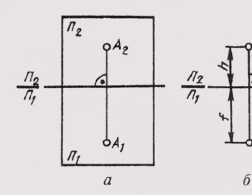
To get a flat drawing, we combine the horizontal projection plane P1 with the frontal plane P2 by rotating around the P2 / P1 axis (Fig. 61, a). Then both projections of the point will be on the same line perpendicular to the P2/P1 axis. The straight line A1A2 connecting the horizontal A1 and frontal A2 projections of the point is called the vertical line of communication.
The resulting flat drawing is called a multidrawing. It is an image of an object on several combined planes. A complex drawing consisting of two orthogonal projections connected to each other is called a two-projection one. In this drawing, the horizontal and frontal projections of the point always lie on the same vertical connection line.
Two interconnected orthogonal projections of a point uniquely determine its position relative to the projection planes. If we determine the position of the point a relative to these planes (Fig. 61, b) its height h (AA1 \u003d h) and depth f (AA2 \u003d f), then these values \u200b\u200bin the complex drawing exist as segments of a vertical communication line. This circumstance makes it easy to reconstruct the drawing, i.e., to determine the position of the point relative to the projection planes from the drawing. To do this, it is sufficient at point A2 of the drawing to restore the perpendicular to the plane of the drawing (considering it to be frontal) with a length equal to the depth f. The end of this perpendicular will determine the position of point A relative to the plane of the drawing.
2. essence of orthogonal projection
The essence of the orthogonal projection method is that
An object is projected onto two mutually perpendicular planes by rays,
Orthogonal (perpendicular) to these planes..
One of the projection planes H is placed horizontally, and the second V -
vertically. The plane H is called the horizontal plane of projections, V -
Frontal. The planes H and V are infinite and opaque. Intersection line
The projection planes is called the coordinate axis and is denoted OX. planes
Projections divide space into four dihedral angles - quarters.
Rectangular (orthogonal) projection is a special case of parallel projection.
The projection of an object obtained using this method is called orthogonal.
Orthogonal projection has all the properties of parallel and central projection, and in addition, the right angle projection theorem is true: if at least one side of the right angle is parallel to the projection plane, and the second is not perpendicular to it, then the right angle is projected onto this plane into a right angle.
3. point projections. Private point positions
Coordinates are numbers that correspond to a point for
Determining its position in space or on a surface.
In three-dimensional space, the position of a point is set using
Rectangular Cartesian coordinates x, y and z.
The x-coordinate is called the abscissa, the y-coordinate, and the z-coordinate. Abscissa
X defines the distance from the given point to the plane W, the ordinate y - to
Plane V and applicate z - to the plane H. Taking for the reference of coordinates
Points system shown in the figure, we will make a table of signs of coordinates in
All eight octants. Any point in space A, given by
Coordinates will be denoted as follows: A (x, y, z).
If x = 5, y = 4 and z = 6, then the record will take the following form A (5, 4, 6). This
Point A, all coordinates of which are positive, is in the first octant
The coordinates of point A are at the same time the coordinates of its radius vector
OA with respect to the origin. If i, j, k are unit vectors,
Directed respectively along the coordinate axes x, y, z (figure), then
OA \u003d OAxi + OAyj + OAzk, where OAX,
ОАУ, ОАg - coordinates of the vector ОА
Construction of the image of the point itself and its projections on the spatial
Rectangular parallelepiped. First of all, on the coordinate axes from the point O
Set aside segments, respectively, equal to 5, 4 and 6 units of length. On these
Segments (Oax, Oay, Oaz), as on edges, build a rectangular
Parallelepiped. Its vertex, opposite to the origin, will be
Determine the given point A. It is easy to see that to determine the point A
It is enough to build only three edges of the parallelepiped, for example Oax , axa1
And a1A or Oay, aya1 and a1A, etc. These edges form a coordinate
A broken line, the length of each link of which is determined by the corresponding
Point coordinate.
4. straight projection. Positions of lines relative to projection planes
A straight line is defined by two points. Therefore, if there is a plan and facade (combined) of two points a and b lying on a line, then the line a'b" connecting the plans of points a and b will be the plan of line ab and the line a"b" connecting the facades of points a and b, will be the façade of the line ab In figure 4, the line ab is shown in its plan and façade.

5. mutual position of straight lines
A line can lie in a plane, be parallel to it, or intersect a plane.


6. ways to specify a plane in the drawing
The position of the plane in space is determined by: three points that do not lie on one line (1), a line and a point taken outside the line (2), two intersecting lines (3), two parallel lines (4), a geometric figure (5), traces plane (6).

7. different cases of the location of the planes relative to the projection planes
Relative to the projection planes, the straight line can occupy a different position. A straight line that is not parallel to any of the main projection planes (see Fig. 69) is called a straight line in general position. A straight line, parallel or perpendicular to one of the projection planes, is called a straight line of particular position.
Lines parallel to one of the projection planes are called level lines. Their name depends on which plane they are parallel to. A straight line parallel to the horizontal plane of projections is called a horizontal line and is indicated in the drawings h (Fig. 70).
A straight line parallel to the frontal projection plane is called the frontal and denoted by f (Fig. 71).


A straight line parallel to the profile plane of the projections is called the profile plane and is denoted by p (Fig. 72).
A level line has one projection parallel to the line itself and determines the angles of inclination of this line to two other projection planes.
The parallelism of one of the projection planes determines the location of the other two projections of the direct level:
h2 || P2/P1 ;
h3 _|_ P2/P3 ;
f2 || P2/P1;
f3 _|_ P2/P3 ;
p1 _|_ P2/P1 ;
p2 _|_ P2/P1 ;
Straight lines h2 and f1 are perpendicular to the vertical communication lines; p1 and p2 are located on the same vertical line of communication and, in a two-projection drawing, must be determined by two points of the straight line p.
Straight lines perpendicular to one of the projection planes are called projecting. These lines, being perpendicular to one projection plane, turn out to be parallel to two other projection planes. Therefore, for projecting lines, one projection turns into a point, and the other two projections are parallel to itself.

Direct and coincide in the drawing with the direction of the communication line (Fig. 73). There are horizontally projecting lines (AB), frontally projecting lines (CD) and profile projecting lines (EF).
8. mutual arrangement of a straight line, a point and a plane. Main lines of the plane
Among the straight lines belonging to the plane, straight lines occupying a particular position in space are of particular importance:
1. Horizontals h - straight lines lying in a given plane and parallel to the horizontal plane of projections
2. Frontals f - straight lines located in the plane and parallel to the frontal plane of projections
Profile lines p - straight lines that are in a given plane and are parallel to the profile plane of projections
It should be noted that traces of the plane can also be attributed to the main lines. The horizontal trace is the horizontal of the plane, the frontal is the front and the profile is the profile line of the plane.
Mutual position of a point and a plane
There are two options for the mutual arrangement of a point and a plane: either the point belongs to the plane, or it does not.
If the point belongs to the plane, then only one of the three projections that determine the position of the point in space can be arbitrarily set.
9. parallel line and plane
A line and a plane are said to be parallel if they do not intersect.
Theorem 1. If a line that does not belong to a plane is parallel to some line in this plane, then it is also parallel to the plane itself.

Proof. Let a be a plane, a a line not lying in it, and b a line in a plane parallel to a. Draw the plane b through the lines a and b. Plane a and b intersect along the line b. If the line a intersects the plane a, then the point of intersection would belong to the line b. But this is impossible, because lines a and b are parallel. So, the line a does not intersect the plane a, and therefore is parallel to it. The theorem has been proven.
10. intersection of two planes
Two planes intersect in a straight line. To build a line of their intersection, you need to find two points that belong to this line. The task is simplified if one of the intersecting planes occupies a particular position. In this case, its degenerate projection includes the projection of the line of intersection of the planes.
On fig. 122 shows a complex drawing of two intersecting planes £ and 0, and the plane Sum of a particular position is frontally projecting. It intersects the lines AB and AC of the plane 0 given by the triangles ABC - the plane in general position. Intersection points 1 and 2 and define the line of intersection of the planes. Connecting them, we get the required line: a(1, 2) = Sum^Q.
The line of intersection of two planes occupying a common position can be constructed in the original system of projection planes. For this, the problem of constructing a straight line of one plane with the second plane is solved twice. The problem can be solved in new system projection planes by constructing an image of one of the intersecting planes as a projection plane.
On fig. 123, and the line of intersection of two triangles ABC and DEF is constructed by constructing the point M of the intersection of the line AB with the plane DEF and the point N of the intersection of the line EF with the plane ABC:
1) AB ~ Sum1(Sum1_|_P2), Sum1 ^DEF=l -2(12-22; 11-21), 11-21 ^ A1B1 = M1, M1,M2 || A1A2,M1M2 ^ A2B2 = M2,M(M,M2);


2) EF ~ Sum2(Sum2_|_П2), Sum2 ^ ABC = 3-4(32-42; 31-41),31-41 ^ E1F1= = N1, N1N2 || A1,A2; N1N2^ E2F2 = N2; N(N1,N2);
3) M1 U N1, = M1N1, M2 U N2 = M2N2;
4) ABC^DEF = MN.
After construction, the visibility of intersecting planes is determined. On the frontal plane, it is determined using frontally competing points 1 and 5. To determine the visibility on the horizontal projection plane, horizontally competing points 6 and 7 are used.
On fig. 123b, the same line of intersection is constructed using additional projections of these planes on the P4 plane, relative to which the DEF plane occupies a projecting position. Additional projections are built from the condition that the horizontal h ? DEF is projected to a point on the plane П4 _|_ h. New communication lines are drawn through irreplaceable horizontal projections of points A,
B, C, D, E, F are parallel to h1, and the new projection axis П1/П4 _|_ h1. The heights of the points measured on the P2 plane determined their projections on the P4 plane.
A4B4C4 ^ D4E4F4 = M4K4, since A4B4 ^ D4E4F4 = M4 and B4C4 ^ D4E4F4 = K4. In the direction of new communication lines, we determine the horizontal projection of the MK line (M1K1). We mark the point of intersection of the side EF with the line MK: E1F1 ^ M1K1 = N1. The points of the segment NK do not have common points with the plane DEF.
Intersecting planes in a particular case can be perpendicular. To identify cases of perpendicularity, it must be remembered that if two planes are mutually perpendicular, then one of them passes through a perpendicular to the other plane. On fig. 122 is a complex drawing of mutually perpendicular intersecting planes: one frontally projecting Sum (Sum2), and the second - in general position (ABC) - contains the perpendicular AB to the plane Sum (AB||P2; A2B2Sum2).
Two planes can generally intersect at infinity. Then the parallelism of these planes takes place. When identifying this case, it should be taken into account that for parallel planes, two intersecting lines of one plane are parallel to two intersecting lines of another plane. On fig. 91 the plane S is parallel to the plane Sum2, since a || c, b || d.
11. parallelism of two planes
Two planes are called parallel if they have no common points.
Theorem 2.6. A sign of parallel planes.
If the plane α is parallel to each of two intersecting lines lying in the other plane β, then these planes are parallel.
Proof

Drawing 2.3.1.
We will prove by contradiction. Let lines a and b lie in the plane β, and let a || α and b || α (drawing 2.3.1). If the planes α and β are not parallel, then they intersect along some line c. Because a || α, then by the trace theorem c || a. Similarly, we obtain that c || b , then a || b. We have arrived at a contradiction, since a and b intersect by assumption.
Theorem 2.7.
If two parallel planes are crossed by a third, then it leaves parallel traces on these planes.

Drawing 2.3.2.
Proof
Let α and β be parallel, γ be the third plane that intersects them, and α γ = a , β γ = b . Thus, a and b are traces of the plane γ on the planes α and β. The lines a and b lie in the same plane γ and have no common points, since the planes α and β have no common points. Therefore, a || b.
Theorem 2.8.
Through a point outside a given plane, one can draw a plane parallel to the given one, and moreover, only one.
Theorem 2.9.
Segments of parallel lines bounded by two parallel planes are equal.

Drawing 2.3.3.
Theorem 2.10.
Two angles with respectively parallel and equally directed sides are equal and lie in parallel planes.
Proof

Drawing 2.3.4.
The drawing 2.3.4 shows the angles BAC and B 1 A 1 C 1, with AB || A 1 B 1 and AC || A 1 C 1. On the basis of the parallelism of the planes, the BAC plane is parallel to the plane B 1 A 1 C 1.
Let the corresponding segments on the sides of the angle be equal: AB = A 1 B 1 and AC = A 1 C 1. Draw lines AA 1, BB 1, CC 1. The quadrilateral ABB 1 A 1 is a parallelogram, since AB = A 1 B 1 and AB || A 1 B 1, therefore, AA 1 = BB 1 and AA 1 || BB 1. We prove similarly that AA 1 = CC 1. This implies that BB 1 = CC 1 and BB 1 || CC 1, therefore, CBB 1 C 1 is a parallelogram and CB = C 1 B 1. Now we assert that Δ ABC = Δ A 1 B 1 C 1, whence BAC = B 1 A 1 C 1.
12. ways to convert a drawing
The transformation of the drawing can be performed by the method of rotation, the method of projection onto an additional plane, the method of plane-parallel transfer, and others. The most commonly used method of rotation and the method of projection onto an additional plane.
13. polyhedra. Points on the surface of polyhedra
Three definitions
A polyhedron, more precisely a three-dimensional polyhedron, is a collection of a finite number of flat polygons in a three-dimensional Euclidean space such that:
Each side of any of the polygons is at the same time the side of the other (but only one), called adjacent to the first (along this side);
(connectivity) from any of the polygons that make up the polyhedron, one can reach any of them by passing to the one adjacent to it, and from this, in turn, to the one adjacent to it, etc.
These polygons are called faces, their sides are called edges, and their vertices are the vertices of the polyhedron. The simplest examples of polyhedra are convex polyhedra, i.e. the boundary of a bounded subset of the Euclidean space, which is the intersection of a finite number of half-spaces.
The given definition of a polyhedron takes on a different meaning depending on how the polygon is defined, the following two options are possible:
Flat closed broken lines (even if they are self-intersecting);
Parts of the plane bounded by broken lines.
In the latter case, a polyhedron is a surface composed of polygonal pieces.
If this surface does not intersect itself, then it is the complete surface of some geometric body, which is also called a polyhedron; hence the third definition arises.
[edit]
Variations and Generalizations
The concept of a polytope is inductively generalized in dimension, and is usually called an n-dimensional polytope.
An infinite polyhedron admits in its definition a finite number of unbounded faces and edges
Curvilinear polyhedra allow curvilinear edges and faces.
Spherical polyhedron.
14. axonometric projections
Axonometric projection (Greek άχοπ - “axis” and “metry”) is a way of depicting geometric objects in a drawing using parallel projections.
An object with the coordinate system to which it is assigned is projected onto an arbitrary plane (the picture plane of the axonometric projection) in such a way that this plane does not coincide with its coordinate plane. In this case, two interconnected projections of one figure onto one plane are obtained, which makes it possible to restore the position in space, obtaining a visual image of the object. Since the picture plane is not parallel to any of the coordinate axes, there are distortions of segments along the length parallel to the coordinate axes. This distortion can be equal along all three axes - an isometric projection, identical along two axes - a dimetric projection, and with different distortions along all three axes - a trimetric projection.
15. format. Scale. Line examples
Scale (German Maßstab, lit. "measuring stick": Maß "measure", Stab "stick") - in the general case, the ratio of two linear dimensions. In many areas practical application scale is the ratio of the size of an image to the size of the object being depicted.
The concept is most common in geodesy, cartography and design - the ratio of the natural size of an object to the size of its image. A person is not able to depict large objects, such as a house, in full size, therefore, when depicting a large object in a drawing, drawing, layout, and so on, a person reduces the size of the object several times: two, five, ten, one hundred, one thousand, and so on. further times. The number showing how many times the depicted object is reduced is the scale. The scale is also used when depicting the microworld. Man cannot picture living cell, which is examined in a microscope, in full size and therefore increases the size of its image several times. The number showing how many times the increase or decrease in a real phenomenon was made when it was imaged, defined as a scale.
Paper size - a standardized size of a paper sheet. Different countries adopted different formats as standard at different times. Currently, two systems dominate: the international standard (A4 and related) and the North American.
1. Solid thick main - used to draw lines of a visible contour, contour lines of sections. With this line you will outline the inner frame of the drawing, the columns of the title block. The thickness of the solid main line (S) is selected in the range from 0.5 to 1.4 mm.
2. A solid thin line is intended for drawing dimension and extension lines, hatching, drawing shelves of leader lines, for depicting imaginary transition lines from one surface to another. The line thickness is selected from S/3 to S/2.
3. A solid wavy line is used to depict a break line, distinguish between a view and a section. Line thickness from S/3 to S/2. This type of line is done by hand.
4. Solid thin with a break. This line represents the long lines of the cliff. Line thickness from S/3 to S/2.
5. The dashed line is used to depict lines of an invisible contour, invisible transition lines. The length of the stroke is chosen from 2 to 8 mm, the distance between the strokes is from 1 to 2 mm. Line thickness from S/3 to S/2.
6. An open line is intended to depict the location of the cutting plane when constructing sections and cuts. Line thickness from S to 1.5 S.
7. A dash-dotted thin line is used to display center and center lines. The stroke length is selected from 5 to 30 mm, the distance between the strokes is from 3 to 5 mm. Strokes alternate with dots. Line thickness from S/3 to S/2.
When depicting a circle, the strokes of the dash-dotted line should intersect in the center of the circle, and therefore the line is called the dash-dotted center line, thereby emphasizing its purpose (Fig. 31).
The dash-dotted (axial and center) line should protrude beyond the contours of the image of objects by 3-5 mm (Fig. 31, a). If it is necessary to set the center of the circle for a hole with a diameter of less than 12 mm, then the center lines are performed with one stroke (Fig. 31, b). Figure 31 shows the drawing of center and center lines.
8. A dashed-dot thickened line is used to depict a surface to be heat treated or coated (not used in the school course).
9. A dash-dotted thin line with two points is used to depict fold lines on reamers, to depict parts of products in extreme or intermediate positions. Stroke length from 5 to 30 mm, distance between strokes from 4 to 6 mm. Line thickness from S/3 to S/2.
16. views. Definition. Classification
A view is an image of the visible part of the surface of an object facing the observer.
The initial view in the drawing is the front view, which is also called the main view. If you look at the object from the left, at a right angle to the profile plane of the projections, you get a view from the left. When looking at an object from above, perpendicular to the horizontal projection plane, a top view is obtained.
The directions in which they look at the part, getting one or another view. Each view occupies a strictly defined place in the drawing in relation to the main view. The left view is placed to the right of the main view and on the same level with it, the top view is placed under the main view. You can not violate this rule by placing views in arbitrary places without special designation.
Knowing the rule for the arrangement of views, it is possible to represent the shape of an object from its flat images. To do this, you need to compare all the views given in the drawing and recreate in the imagination the three-dimensional shape of the object. Along with front, top and left views, right, bottom, back views can be used to depict an object - all of them are called basic. However, the number of views in the drawing should be the smallest, but sufficient to fully reveal the shape and size of the object.
17. main and local views
In some cases, in the drawing, instead of a full view, you can apply a part of it. This simplifies the construction of the image of the subject.
The image of a separate, limited place on the surface of an object is called a local view.
It is used when it is required to show the shape and dimensions of individual elements of the part (flange, keyway, etc.).
The local view can be limited by a cliff line, an axis of symmetry, and so on. A local view is placed on a free field of the drawing or in a projection connection with other images. The use of a local view allows you to reduce the amount of graphic work, save space on the drawing field.
The following names of the main types are established:
Front view (main view) - image on the frontal plane
Top view - image on a horizontal plane
Left view - image on the profile plane
Right view - image on the profile plane
Bottom view - image on a horizontal plane
Rear view - image on the frontal plane
18. additional view
AUXILIARY VIEW is a projection of the model along the edge or line of the main view. An additional view is created by clicking the Additional View button on the Drawing Views toolbar and must be aligned with the base view. Options for creating an additional view are set in the Additional View dialog box:
The name is the area in which
Holding on:
Name - a text box for specifying the designation of an additional view in accordance with the applied design standard. The user can define a new designation for the additional view;
Visibility - a checkbox, the setting of which ensures that the designation of an additional view is displayed on the drawing.
19. cut
A cut is a mental section of an object by one or more planes. The section shows those parts and their parts that are located behind the cutting plane.
A section (architectural, frontal projection of a building or architectural detail conditionally dissected by a plane or a system of planes) serves to conditionally depict the configuration of architectural details, volumes or internal spaces in the drawing and characterizes the shape and configuration of the structure.
Incision types
Simple cut
A section is simple in the drawing
1. Depending on the number of cutting planes, the cuts are divided into:
Simple cut - one plane is used for shaping.
Complex cut - two or more cutting planes are used to form.
Broken cut - two (more rarely used) intersecting planes are used to form.
Stepped cut - two or more parallel planes are used for formation.
2. Depending on the position of the plane relative to the horizontal projection plane, the sections are divided into:
Horizontal - the cutting plane is parallel to the horizontal projection plane.
Vertical - the cutting plane is perpendicular to the horizontal projection plane.
Inclined - the cutting plane makes an angle with the horizontal plane that is different from the right one.
3. Depending on the position of the cutting plane relative to the main dimensions of the object, sections are distinguished:
Longitudinal - the cutting plane is directed along the length or height of the object.
Transverse - the cutting plane is perpendicular to the length or height of the object.
4. Depending on the completeness of the image, the cuts are:
Full - the cutting plane intersects the entire object and the image of its internal structure is shown throughout the section.
Local - the cutting plane intersects only that part of the object in which it is required to show its internal shape. The boundaries of the local section are shown as a thin solid wavy line.
20. simple cut (see 19.)
21. complex cut (see 20)
22. remote elements, designation
A remote element is an additional separate image of any part of an object that requires clarification regarding the shape, size and other data.
The detail view is drawn on a larger scale with all the necessary dimensions and details that cannot be shown on the main image.
The detail element may differ from the corresponding image in terms of content, i.e. the original image can be a view, and the detail element can be a section, etc.
23. section
Section - an image of a figure obtained by mentally dissecting an object with a cutting plane. The section shows only what is in the cutting plane.
The part is projected onto the projection plane V. Then it is mentally cut by a secant plane in the place where it is necessary to clarify the shape of the product. In the cutting plane, a section figure is obtained. After that, the cutting plane (together with the figure of the section) is mentally taken out, rotated around vertical axis, move parallel to the projection plane and align with the V plane so that the images of the front view and the section figure do not obscure each other (). Note that with this movement of the cutting plane, the front view is in projection relationship with the section. The resulting image of the section figure is called a section made in a projection connection.
It is allowed to move the cutting plane with the section figure in any direction, aligning it with the projection plane, without taking into account the projection connection. Such a section is called a section made in the free space of the drawing (Fig. 148, c). The section can also be placed on the continuation of the trace of the cutting plane (It is called the section made on the continuation of the trace of the cutting plane.
If the section is located on the continuation of the trace of the cutting plane, then the section is not denoted (). If the section is located in a free place in the drawing, then it is designated with an inscription of the type "A - A" (
If the cutting plane passes along the axis of a cylindrical or phonic surface that bounds a hole or recess, then their contour on the section is shown in full, for example, the image of a conical recess.
When performing various images of an object, GOST 2.305-68 recommends using some conventions and simplifications, which, while maintaining the clarity and clarity of the image, reduce the amount of graphic work.
If the view, section or section are symmetrical figures, then only half of the image or slightly more than half of the image can be drawn, limiting it with a wavy line
Simplification is allowed to depict cut lines and transition lines; instead of curved curves, arcs of a circle and straight lines are drawn, and a smooth transition from one surface to another is shown conditionally (or not shown at all (
It is allowed to depict a slight taper or slope enlarged. On those images where the slope or taper is not clearly detected, only one line is drawn, corresponding to the smaller size of the element with a slope (, a) or the smaller base of the cone (
When making cuts, non-hollow shafts, handles, screws, dowels, and rivets are shown undissected. Balls are always depicted uncut.
Elements such as knitting needles, thin walls, stiffeners are shown unshaded in the section if the cutting plane is directed along the axis or long side of such an element (. If there is a hole or recess in such elements, then a local cut is made (
Holes located on a circular flange and not falling into the cutting plane are shown in section as if they were in the cutting plane
To reduce the number of images, it is allowed to depict the part of the object located between the observer and the cutting plane as a dash-dot thickened line (). In more detail, the rules for the image of objects are set out in GOST 2.305-68.
25. sketch
Sketch (fr. esquisse) - a preliminary sketch that fixes the idea of a work of art, structure, mechanism or a separate part of it. A sketch is a quickly done freehand drawing, not meant to be a finished work, often consisting of many overlapping lines.
Sketches are inexpensive and allow the artist to sketch and try out other ideas before turning them into a painting. Pencil or pastel is preferred for sketching due to time constraints, but a quick watercolor sketch, or even a quick modeled layout in clay or soft wax, can also be considered a sketch in the broader sense of the word. Graphite pencils are a relatively new invention, Renaissance artists made sketches using a silver pen on specially prepared paper.
Contrary to popular belief, artists often use erasers when drawing. The eraser can be used to remove construction lines, or to soften lines that are too sharp.
26. detailing
The manufacture of parts included in the product is carried out according to the working drawings, which are drawn up according to the assembly drawing. Drawing working drawings from an assembly drawing is called detailing.
Before proceeding with detailing, you need to carefully study the assembly drawing, find the details in all projections, understand how they are interconnected and what role they play in the product. Before detailing, it is necessary to resolve the issue, c. how many projections and on what scale each detail should be drawn, and based on the overall dimensions of the detail, determine on what paper format it can be drawn. When detailing, it is desirable that the details be drawn in full size, that is, on a scale of 1: 1. Large details are drawn on a reduced scale. Small details in some cases should be drawn even on an enlarged scale against nature, so that the completed drawing can be easily read. When the issue of the format for each individual part is decided, the total number of A1 sheets required for detailing must be established. The breakdown of a sheet of paper should not be done abstractly, but taking into account the formats required for each detail. Therefore, sheet a1 can contain all sizes, from a2 for large parts to a5 for small parts. On each format intended for the image of a detail, the main inscription (stamp) in accordance with GOST must be placed.
On the drawings of those parts that are processed together with other parts not during assembly, appropriate instructions should be given, for example: Boring together with det. 15.
If the finished parts require the preservation of center nests, then the latter are depicted on the drawing according to OST 3725.
If the finished parts should not have center sockets, then this is indicated on the drawing by the inscription: Center sockets are not allowed.
If it is structurally indifferent whether center nests should or should not be left, then they are not shown on the drawing of the part and are not specified in any notes.
On the working drawings of the parts, the dimensions that determine the location of the mating surfaces should be marked, as a rule, from the structural bases, taking into account the possibility of their observance and control
It is not allowed to put dimensions in the drawings in the form of a closed chain or enter repeating dimensions.
Dimensions related to the same part element (groove, recess, etc.) are recommended to be grouped on one projection, giving preference to the projection on which this element is shown most clearly.
When detailing an assembly drawing, there can be two cases:
1) if the number of parts of a given assembly unit is small, then the drawings of the parts are placed on one sheet with the assembly drawing. The assembly drawing in this case is drawn on the right in the lower half of the sheet;
2) if the product consists of a large number of parts, then their drawings are placed on a separate sheet or on several sheets.
When detailing assembly drawings, first of all, you should draw the main part, for example, the body, since the dimensions of the main part are associated with the dimensions of the parts associated with it, as well as the selection and appointment of landings and signs of cleanliness of surface treatment. This is also important because the dimensions of all parts must be mutually linked. For example, if two parts are bolted together, then the distance between the axes of the bolt holes and the diameters of the holes through which the bolts pass must be the same in the connected parts.
The working drawing, in addition to the image of the part, must also contain the dimensions, tolerances, designations of surface cleanliness necessary for its manufacture and control, data on the material, heat treatment, finish and other technical requirements for the finished part, if the latter are not included in the technical specifications.
Regardless of the accepted scale, only the actual dimensions are affixed to the working drawings of the parts.
The dimensions of the mating elements of the part must be provided with tolerances and fits. Tolerances for linear dimensions, distances between holes, etc., must also be indicated. An exception is the dimensions that define zones of varying degrees of surface finish on the same surface, heat treatment zones, finishes, sizes of irresponsible chamfers and rounding radii, etc., which can be affixed without permissions.
P p and m e h a n and i. 1. It is allowed not to affix directly to the dimensions, but to stipulate with the appropriate general inscription on the free field of the drawing separate, widely used categories of tolerances, for example: tolerances for free dimensions, tolerances for dimensions of cast raw elements of a part, etc. At the same time, references to factory or departmental normals are not allowed.
2. Free dimensions are those that are not included in the dimensional chains and do not directly affect the nature of the connection of parts (
If in parts made from sheet, rolled, calibrated or other types of standard material profiles, individual parts are not processed, then dimensions, as a rule, are affixed without tolerances.
In some cases, when the design conditions require these tolerances, such dimensions are affixed with the tolerances that are established by the relevant standards or specifications for the material profiles used.
If the required accuracy or other operational qualities of the connection are achieved by selection, fitting, etc., then it is necessary to give instructions in the drawings regarding the nature of the interfaces, the method of their provision and the method of control.
When applying signs of processing cleanliness in accordance with GOST 2789-45, you should not indicate increased cleanliness of processing, where this is not required, so as not to increase the cost of manufacturing the part.
If the surfaces of the part must be treated in the same way, then it is written on the drawing: in a circle indicating the degree of purity of processing with conventional signs (
When drawing, you need to show sections of the part, if necessary, and in some cases, sections of individual places. They will bring clarity to the outlines of the part.
27. carving
Thread - evenly spaced protrusions or cavities of a constant section, formed on a lateral cylindrical or conical surface along a helical line with a constant pitch. It is the main element of the threaded connection, screw gear and worm of the gear-screw drive.
Classification and main features of threads
Pitch unit (metric, inch, modular, pitch thread)
Surface location (external and internal thread)
The direction of movement of the helical surface (right, left);
Number of runs (single and multi-start), for example, two-start, three-start, etc.;
Profile (triangular, trapezoidal, rectangular, round, etc.);
The forming surface on which the thread is located (cylindrical thread and conical thread);
Appointment (fixing, fixing and sealing, chassis, etc.).
28.thread designation
A monge diagram or a complex drawing is a drawing composed of two or more interconnected orthogonal projections of a geometric figure.
Using a spatial layout to display orthogonal projections of geometric figures is inconvenient due to its bulkiness, and also due to the fact that when it is transferred to a sheet of paper, the shape and size of the projected figure is distorted on the H and W planes.
Therefore, instead of the image in the drawing of the spatial layout, the Monge diagram is used.
The Monge diagram is obtained by transforming the spatial layout by combining the H and W planes with the frontal projection plane V:
- to align the H plane with V, rotate it 90 degrees around the x axis in the clockwise direction. In the figure, for clarity, the plane H rotated at an angle slightly less than 90 degrees, while the axis y, belonging to the horizontal projection plane, after rotation coincides with the axis z;
- after aligning the horizontal plane, rotate around the axis z also at an angle of 90 degrees to the profile plane in the direction opposite to the clockwise movement. At the same time, the axis y, belonging to the profile plane of the projection, after rotation coincides with the axis x.
After the transformation, the spatial layout will take the form shown in the figure. This figure also shows the sequence of the relative position of the floor of the projection planes, so the record V indicates that in this part of the Monge plot (limited by the positive direction of the axes x And z) closer to us is the upper left floor of the frontal projection plane V, behind it is the rear left floor of the horizontal projection plane H, followed by the upper rear floor of the profile plane W.
Since the planes do not have boundaries, then in the combined position (on the diagram) these boundaries are not shown, there is no need to leave inscriptions indicating the position of the floor of the projection planes. It is also superfluous to remind where the negative direction of the coordinate axes is. Then, in its final form, the Monge diagram replacing the spatial layout drawing will take the form shown in the figure. 
The Monge plot can be done with:
- conventional drawing tools and fixtures:
Drawing tools;
Drawing accessories and devices;
- Programs for building (drawing) the Monge diagram: Making a drawing in a graphics editor.
As an example of the design of the Monge diagram, we offer a solution to the problem of constructing an isosceles right triangle ABC: 
— the known by the condition of the problem is displayed in black;
- in green color all the constructions that lead to the solution of the problem are displayed;
- the searched tasks are displayed in red.
According to the condition of the problem, the projections of the triangle ABC(A`B`C`, A»B»…”) are given. To solve the problem, it is necessary to find the missing projection C.
Monge method, complex drawing.
Point projections, complex drawing.
Mutually perpendicular projection planes.
Methods of rectangular projection on two and three
Orthographic projection properties
Basic and unchangeable properties The (invariants) of orthogonal projection are the following:
1) point projection - point;
2) the projection of a straight line - in the general case, a straight line; if the direction of projection coincides with the direction of the straight line, then the projection of the latter is a point;
3) if a point belongs to a line, then the projection of this point belongs to the projection of the line.
4) projections of parallel lines are parallel to each other;
5) the ratio of line segments is equal to the ratio of their projections;
6) the ratio of segments of two parallel lines is equal to the ratio of their projections;
7) the projection of the point of intersection of two lines is the point of intersection of the projections of these lines;
8) if a straight or flat figure is parallel to the plane of projections, then they are projected onto this plane without distortion;
9) if at least one side of the right angle is parallel to the plane of projections, and the second is not perpendicular to it, then the right angle is projected onto this plane into a right angle.
If information about the distance of a point relative to the projection plane is given not with the help of a numerical mark, but with the help of the second projection of the point built on the second projection plane, then the drawing is called two-picture or comprehensive. The basic principles for constructing such drawings are set out Gaspard Monge - a major French geometer of the late 18th, early 19th centuries, 1789-1818. one of the founders of the famous Polytechnic School in Paris and a participant in the work on the introduction of the metric system of measures and weights.
The gradually accumulated separate rules and techniques of such images were brought into the system and developed in the work of G. Monge "Geometrie descriptive".
Monge's method of orthogonal projection onto two mutually perpendicular projection planes was and remains the main method for drawing up technical drawings.
In accordance with the method proposed by G. Monge, we consider two mutually perpendicular projection planes in space (Fig. 6). One of the projection planes P 1 placed horizontally, and the second P 2 - vertically. P 1 - horizontal projection plane, P 2 - frontal. The planes are infinite and opaque.
Projection planes divide space into four dihedral angles - quarters. Considering orthogonal projections, it is assumed that the observer is in the first quarter at an infinitely large distance from the projection planes.
| Figure 6. Spatial model of two projection planes | The line of intersection of the projection planes is usually called the coordinate axis and is denoted x 21 . Since these planes are opaque, only those geometric objects that are located within the same first quarter will be visible to the observer. To get a flat drawing consisting of the specified projections, the plane P 1 combine by rotation around the axis x 12 with flat P 2 (Fig. 6). A projection drawing, on which the projection planes with everything that is shown on them, combined in a certain way with one another, is commonly called Monge diagram(French Epure - drawing.) Or a complex drawing. |
Monge method, complex drawing. - concept and types. Classification and features of the category "Monge method, complex drawing." 2017, 2018.
INTRODUCTION ................................................ ................................................. ....4
1 METHODOLOGICAL INSTRUCTIONS FOR SOLVING PROBLEMS.................................4
2 ADOPTED SYMBOLS .............................................................. ...................5
3 TOPIC 1 COMPLEX DRAWING OF MONGE (point, line) .......6
3.1 Complex drawing of a point. ........ .......................................... ...................6
Exercises. ................................................. ................................................. ..6
Tasks. ................................................. ................................................. ............7
Examples of problem solving…………………………………...................................................8
Knowledge Self-Control Tests…………………………………………………………………………………………………………………………………………………………………………………………………………………………………………………………………………………………………………………………………………………………………………………………………………………………………………………………………………………………………………………………………………………………………………………………………………………………………………………………………………………………………………………………………………10
3.2 Complex drawing of a straight line .......................................................... ....................eleven
Exercises. ................................................. ................................................. .eleven
Tasks. ................................................. ................................................. ...........12
Examples of problem solving…………………………………...................................13
Knowledge self-control tests…………………………………………………………………………………………………………………………………………………………………………………………………………………………………………………………………………………………………………………………………………………………………………………………………………………………………………………………………………………………………………………………………………………………………………………………………………………………………………………………………………………………………………………………………………………………………………15
4 TOPIC 2 COMPLEX DRAWING OF MONGE (PLANE) ....... 17 PERPENDICULARITY OF RIGHTS AND PLANES
4.1 Complex drawing of a plane .......................................................... ..............17
Exercises. ………………………………………………………………………. ....................................17
Tasks. …................................................. ................................................. ........19
Examples of solving problems ................................................................................. 21
Tests of self-control of knowledge………………………………….......................21
4.2 Perpendicularity of lines and planes..............................................................23
Exercises. ................................................. ................................................. .23
Tasks. …................................................. ................................................. ........24
Examples of solving problems ............................................................................... 25
Self-control tests of knowledge………………………………………………………………………………………………………………………………………………………………………………………………………………………………………………………………………………………………………………………………………………………….
5 TOPIC 3 Mutual position of lines AND PLANES
Exercises. ................................................. ................................................. .27
Tasks. ................................................. ................................................. ...........29
Examples of problem solving. ................................................. ...............................thirty
Knowledge Self-Control Tests………………………………………………………………………………………………………………………………………………………………………………………………………………………………………………….
6 TOPIC 4 WAYS TO CONVERT A DRAWING .......................33
Exercises. ................................................. ................................................. .33
Tasks................................................. ................................................. ............34
Examples of problem solving. ................................................. ...............................36
Tests of self-control of knowledge…………………………………......................38
7 TOPIC 5 MULTIFACETED SURFACES.................................................40
Exercises. ................................................. ................................................. .40
Tasks. ................................................. ................................................. ...........41
Examples of problem solving. ................................................. ...............................43
Tests of self-control of knowledge ............................................... ...............................44
REFERENCES………………...................................................47
APPLICATION.................................................................................................47
INTRODUCTION
Tutorial is intended for laboratory classes in descriptive geometry for students of the Faculty of Land Management and Forestry (directions: 250700 - Landscape Architecture, 250100 - Forestry).
The manual is used by students in self-preparation for the next lesson. To do this, he must:
Study theoretical material on a given topic and answer self-control questions;
Complete the exercises on the given topic.
At the beginning of the lesson, the teacher checks the theoretical preparation of students and the solution of exercises on a given topic. At the end of each topic, examples of solving typical problems. When starting to solve the exercises of a new topic, it is useful to familiarize yourself with the corresponding example and follow it in the design of the drawing.
The manual can also be used by students for self-control of acquired knowledge on tests given in the manual after examples of solving typical problems. To do this, he must:
After each lesson, answer self-control tests of knowledge, and check the correctness of your knowledge using the answers given in the appendix of the manual.
In the process of working with the manual, students learn practical techniques used in solving problems, which allows them to develop the skills and abilities to solve them independently. As this experience accumulates, students begin to think independently at a professional level, while developing spatial and logical thinking.
METHODOLOGICAL INSTRUCTIONS FOR SOLUTION AND
FORMING TASKS
When solving problems, you should be guided by the following recommendations:
1. According to the projections of geometric figures that make up the initial data of the problem, imagine their shape and relative position in space both in relation to each other and relative to the projection planes.
2. Outline a "spatial" plan for solving the problem. At this stage of the solution, one should refer to the theorems from the course of elementary geometry sections "Planimetry" and "Stereometry", as well as to theoretical material in textbooks and lectures.
3. Determine the algorithm for solving the problem, briefly write down the sequence of graphical constructions using the accepted notation.
4. Proceed to geometric constructions.
When solving a problem graphically, the accuracy of the answer depends not only on the choice of the correct way to solve it, but also on the accuracy of the geometric constructions. Therefore, when solving the problem, it is necessary to use drawing tools. Tasks should be solved in a separate notebook in a cage for laboratory exercises. The type and thickness of the lines are carried out in accordance with GOST 2.303-68 ESKD. Constructions are made in pencil. To make it easier to read the drawing obtained in the process of solving, it is advisable to use colored pencils: the given elements are outlined in black, auxiliary constructions in blue, the desired elements in red. The same goal is pursued by the mandatory designation of all points and lines. In this case, the designation should be done in the process of solving the problem immediately after drawing the line or determining the point of intersection of the lines. Inscriptions and letter designations should be made in standard font in accordance with GOST 2.304-84 ESKD.
A notebook with solved problems is presented to the teacher at the test or exam.
ACCEPTED DESIGNATIONS
A, B, C, D,…or 1, 2, 3, 4, ... - point designation; capital letters of the Latin alphabet or Arabic numerals.
o - image of a point (dot location area); a circle with a diameter of 2-3 mm with a thin line by hand.
a, b, c, d,... - a line in space; lowercase letters of the Latin alphabet.
Γ, Σ, Δ,… - planes, surfaces; capital letters of the Greek alphabet.
α, β, γ, δ, ... - corners; lowercase letters of the Greek alphabet.
P - projection plane (picture plane); capital letter (pi) of the Greek alphabet.
AB- a line passing through the points A And IN .
[AB]- segment bounded by points A And IN .
[AB ) is a ray bounded by a point A and passing through the point IN.
/AB /–natural size of the segment[ AB] (equal to the original).
/Aa /–distance from the point A to the line A.
/AΣ /–distance from the point A up to the plane Σ .
/ab /– distance between lines A And b.
/GD / - distance between surfaces G and D.
≡- coincidence (A≡B - points A and B coincide).
║ - parallel.
^ - perpendicular.
∩ - intersection.
О - belongs to, is an element of the set.
RABC - angle with vertex at point B.
The image of signs must be carried out in accordance with accepted standards for the design of technical and scientific documentation.
SUBJECT 1 INTEGRATED DRAWING OF MONGE
(POINT, DIRECT)
Questions of self-control
1. What is called the projection of a point?
2. What is called the projection axis? What straight lines are called "link lines" and how are they located relative to the projection axis?
3. Can you restore the position of a point in space by its projections?
4. How can you set a straight line on a complex drawing?
5. Which lines are called lines in general position? Name the lines of private position.