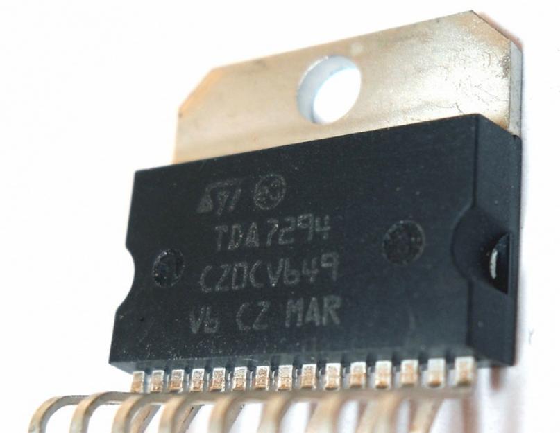
The article is dedicated to lovers of loud and high-quality music. TDA7294 (TDA7293) is a low-frequency amplifier chip manufactured by the French company THOMSON. The circuit contains field-effect transistors, which ensures high sound quality and soft sound. simple circuit, few additional elements make the circuit available for manufacturing to any radio amateur. A properly assembled amplifier from serviceable parts starts working immediately and does not need to be adjusted.

The audio frequency power amplifier on the TDA 7294 chip differs from other amplifiers of this class:
- high output power
- wide supply voltage range,
- low percentage of harmonic distortion,
- "soft sound,
- few "mounted" parts,
- low cost.
It can be used in amateur radio audio devices, when modifying amplifiers, acoustic systems, audio equipment devices, etc.
The figure below shows typical circuit diagram power amplifier for one channel.


The TDA7294 chip is a powerful operational amplifier whose gain is set by a negative feedback circuit connected between its output (pin 14 of the chip) and the inverted input (pin 2 of the chip). A direct signal is input (pin 3 of the microcircuit). The circuit consists of resistors R1 and capacitor C1. By changing the values of the resistances R1, you can adjust the sensitivity of the amplifier to the parameters of the preamplifier.
Structural diagram of the amplifier on the TDA 7294

Technical characteristics of the TDA7294 chip
Technical characteristics of the TDA7293 chip
Schematic diagram of the amplifier on the TDA7294

To assemble this amplifier, you will need the following parts:
1. Chip TDA7294 (or TDA7293)
2. 0.25 watt resistors
R1 - 680 Ohm
R2, R3, R4 - 22 kOhm
R5 - 10 kOhm
R6 - 47 kOhm
R7 - 15 kOhm
3. Film capacitor, polypropylene:
C1 - 0.74 mkF
4. Electrolytic capacitors:
C2, C3, C4 - 22 mkF 50 volt
C5 - 47 mkF 50 volt
5. Resistor variable dual - 50 kOm
On one chip, you can assemble a mono amplifier. To assemble a stereo amplifier, you need to make two boards. To do this, we multiply all the necessary details by two, except for the dual variable resistor and the PSU. But more on that later.
Amplifier printed circuit board on a TDA 7294 chip
The circuit elements are mounted on a printed circuit board made of one-sided foil fiberglass.

A similar circuit, but a little more elements, mostly capacitors. The turn-on delay circuit is enabled at the “mute” input, pin 10. This is done for a soft, pop-free turn-on of the amplifier.


A microcircuit is installed on the board, in which unused conclusions are removed: 5, 11 and 12. Mount with a wire with a cross section of at least 0.74 mm2. The microcircuit itself must be installed on a radiator with an area of at least 600 cm2. The radiator should not touch the amplifier case as it will have a negative supply voltage. The case itself must be connected to a common wire.
If you use a smaller area of the radiator, you must make forced airflow by placing a fan in the amplifier case. The fan is suitable from a computer, with a voltage of 12 volts. The microcircuit itself should be mounted on a heatsink using heat-conducting paste. Do not connect the radiator to live parts, except for the negative power bus. As mentioned above, the metal plate at the back of the microcircuit is connected to the negative power circuit.
Microcircuits for both channels can be installed on one common radiator.
Power supply for the amplifier.
The power supply is a step-down transformer with two windings with a voltage of 25 volts and a current of at least 5 amperes. The voltage on the windings must be the same and the filter capacitors too. Voltage surge must not be allowed. When applying bipolar power to the amplifier, it must be supplied at the same time!

Diodes in the rectifier are better to put ultra-fast, but in principle, conventional ones like D242-246 for a current of at least 10A are also suitable. It is advisable to solder a capacitor with a capacity of 0.01 microfarads in parallel with each diode. You can also use ready-made diode bridges with the same current parameters.
Filter capacitors C1 and C3 have a capacitance of 22,000 microfarads for a voltage of 50 volts, capacitors C2 and C4 have a capacitance of 0.1 microfarads.
The supply voltage of 35 volts should only be at a load of 8 ohms, if you have a load of 4 ohms, then the supply voltage must be reduced to 27 volts. In this case, the voltage on the secondary windings of the transformer should be 20 volts.
You can use two identical transformers with a power of 240 watts each. One of them is used to obtain a positive voltage, the second - a negative one. The power of two transformers is 480 watts, which is quite suitable for an amplifier with an output power of 2 x 100 watts.
Transformers TBS 024 220-24 can be replaced by any other transformers with a capacity of at least 200 watts each. As mentioned above, nutrition should be the same - transformers must be the same!!! The voltage on the secondary winding of each transformer is from 24 to 29 volts.
Amplifier circuit increased power on two TDA7294 chips in a bridge circuit.

According to this scheme, four microcircuits are needed for the stereo version.
Amplifier Specifications:
- Maximum output power at a load of 8 ohms (power supply +/- 25V) - 150 W;
- Maximum output power at a load of 16 ohms (power supply +/- 35V) - 170 W;
- Load resistance: 8 - 16 Ohm;
- Coef. harmonic distortion, at max. power 150 watts, e.g. 25V, load 8 Ohm, frequency 1 kHz - 10%;
- Coef. harmonic distortion, at a power of 10-100 watts, e.g. 25V, load 8 Ohm, frequency 1 kHz - 0.01%;
- Coef. harmonic distortion, at a power of 10-120 watts, e.g. 35V, load 16 Ohm, frequency 1 kHz - 0.006%;
- Frequency range (with non-frequency response 1 db) - 50Hz ... 100kHz.
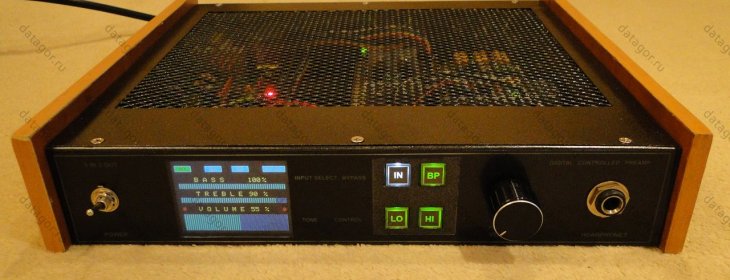
View of the finished amplifier in a wooden case with a transparent plexiglass top cover.

To operate the amplifier at full power, you need to apply the required signal level to the input of the microcircuit, and this is at least 750mV. If the signal is not enough, then you need to assemble a preamplifier for buildup.
Preamplifier circuit on TDA1524A

Setting up the amplifier
A properly assembled amplifier does not need to be adjusted, but no one guarantees that all the parts are absolutely in good order; when you turn it on for the first time, you need to be careful.
The first power-up is carried out without load and with the input signal source turned off (it is better to short the input with a jumper altogether). It would be nice to include fuses of the order of 1A in the power circuit (both in the "plus" and "minus" between the power source and the amplifier itself). We briefly (~0.5 sec.) apply the supply voltage and make sure that the current consumed from the source is small - the fuses do not burn out. It is convenient if the source has LED indicators - when disconnected from the mains, the LEDs continue to burn for at least 20 seconds: the filter capacitors are discharged for a long time by a small quiescent current of the microcircuit.
If the current consumed by the microcircuit is large (more than 300 mA), then there can be many reasons: short circuit in the installation; poor contact in the "ground" wire from the source; mixed up "plus" and "minus"; the pins of the microcircuit touch the jumper; microcircuit is faulty; capacitors C11, C13 are incorrectly soldered; capacitors C10-C13 are faulty.
After making sure that everything is fine with the quiescent current, safely turn on the power and measure the constant voltage at the output. Its value should not exceed + -0.05 V. A large voltage indicates problems with C3 (less often with C4), or with a microcircuit. There were cases when the "inter-ground" resistor was either poorly soldered, or instead of 3 ohms it had a resistance of 3 kOhm. At the same time, the output was a constant of 10 ... 20 volts. By connecting an AC voltmeter to the output, we make sure that the AC voltage at the output is zero (this is best done with the input closed, or simply with the input cable not connected, otherwise there will be noise at the output). The presence of an alternating voltage at the output indicates problems with the microcircuit, or circuits C7R9, C3R3R4, R10. Unfortunately, often ordinary testers cannot measure the high-frequency voltage that appears during self-excitation (up to 100 kHz), so it is best to use an oscilloscope here.
All! You can enjoy your favorite music!
Update- see the bridge version there WK60!!!

What do you think is shown in the photo? So, we don’t tell from the back rows!
In the meantime, we are looking in the search engine for the inscription on the board, I will tell you what it is. This is the UcD250 module from Hypex Electronics.
Nothing special. Class D, 250W advertised power. Normal, right?
Again the Chinese drew their Watts? No, today everything is honest and for real.
These are the insides of an EveAudio near field monitor designed for professional studio work.
The size of the module can be estimated from the photo; for scale, a regular AA battery.
Digitally controlled pre-amplifier. We use with programming through the Arduino shell, electronic potentiometers from Microchip, graphic TFT.
It was not part of my plans to develop and assemble this device. Well, there's just no way! I already have two preamps. Both suit me just fine.
But, as it usually happens with me, a combination of circumstances or a chain of certain events, and now a task has been drawn for the near future.
Hello Datagor readers again! In the second part, we will be engaged in the construction of a 6-channel volume control.

The regulator consists of two main microcircuits: the ATiny26 microcontroller and the specialized TDA7448 chip. I added a volume indicator (a line of 7 LEDs) to roughly know what level is set, because an infinitely rotating encoder acts as a knob.

And then I decided to try 5.1 surround sound. But on a budget, without sacrifice. And rushed! He began to disassemble, pick, design, assemble, saw, drill ... In general, he undertook to pump the system.
I offer the results in two parts to dear readers.
By chance, an Arctur-006-stereo record player fell into my hands. Therefore, there was an urgent need for a phono stage. On the Internet, I came across A. Bokarev's scheme, on which he decided to make a much-needed device.
At the back of the player there are two output connectors (SG-5 / DIN): one from the built-in phono stage (500mV), the second bypass, for connecting to an external one (5mV). When using the built-in phono stage, a jumper is installed in the second output.
I did not like the characteristics of the built-in equalizer, and when I turned it on it turned out that it was faulty - I heard only a 50 Hz rumble in the speakers. There was no desire to restore it, I turned off the built-in corrector board completely.
I will listen to my choice.

Photo source: vega-brz.ru
Since 1983, the Berd radio plant has been producing the electric player of the highest complexity group "Arctur-006-stereo". The player is made on the basis of a two-speed EPU G-2021, with an ultra-low-speed electric motor and direct drive. There is a clamping force regulator and a rolling force compensator, adjusting the disk rotation speed using a strobe light, auto-stop, micro-lift, speed switch and auto-return of the tonearm at the end of the record.
This project considers headphone amplifiers based on mass-produced microcircuits, such as BA5415A and BA5417.

I refrained from philosophical discussions, which of the presented sound reproduction schemes is “more correct”. The purpose of the experiments is different - to provide worthy schemes for repetition, and enthusiastic readers will make their own choice and share their impressions.
Ganichev G.
Moscow
This article continues a series of publications on power amplifiers offered to radio amateurs by MASTER KIT. The article includes two recent developments - NM2042 (powerful low-frequency amplifier 140 W) and NM2043 (powerful car Hi-Fi bridge amplifier low frequency 4x77 W). The amplifiers are designed to meet all the necessary requirements and are made on a modern integrated element base. The proposed PAs have high performance characteristics, high reliability, ease of manufacture/connection and an optimal price/quality ratio, which is an important factor today. Devices can be assembled from MASTER KIT NM2042 and NM2043.
MASTER KIT specialists were assigned and successfully solved the task of preparing technical documentation and producing a VLF line for use in Hi-Fi sound technology. Gradually, the range of these devices is expanding and supplemented by new developments. This article will consider two new developments - and.
All proposed models of power amplifiers have a minimum level of intrinsic noise, a minimum level of non-linear distortion and a wide band of reproducible frequencies. The models differ mainly in terms of maximum output power, supply voltage (bipolar or unipolar “automobile” (14.4 V)) number of amplification channels and external design.
Radio amateurs themselves can breed a printed circuit board, but keep in mind that this is a very responsible and serious job. Not everyone knows that, for example, incorrect routing of printed conductors in a powerful amplifier can increase the level of its non-linear distortion tenfold or even make it completely inoperable. Therefore, professional designers specializing in this field were involved in the development of printed circuit boards.
. Powerful low frequency amplifier 140 W (TDA7293).
The proposed LF amplifier has a minimum coefficient of non-linear distortion and the level of intrinsic noise. The device has small dimensions. A wide range of supply voltages and load resistances expands the scope of this PA. It can be used both outdoors for various events, and at home as part of your musical audio complex. The amplifier has proven itself as a ULF for a subwoofer.
ULF is made on an integrated circuit TDA7293. This IMS is ULF class AB. Due to the wide range of supply voltages and the ability to supply current to the load up to 10 A, the microcircuit provides the same maximum output power at loads from 4 ohms to 8 ohms. One of the main features of this microcircuit is the use of field-effect transistors in the preliminary and output stages of amplification and the possibility of parallel connection of several ICs for operation with a low-resistance load (< 4 Ом).
The operation mode of the IC is controlled using switch SW1. To turn on the ULF, SW1 must be closed. Switch SW2 is provided for technological purposes. For normal operation, SW2 must be bridged in position 2-3.
Coil L1 must be made by yourself. L1 - frameless, three-layer, contains ten turns of PEV-1.0 wire in each layer. Winding must be done on a 12 mm mandrel. Approximate inductance - 5 μH.
The supply voltage is applied to contacts X3(+), X6(-) and X7(common).
The signal source is connected to X1(+) and X2(common).
The load is connected to X4(+) and X5(common).
Structurally, the amplifier is made on a printed circuit board made of foil fiberglass. The design provides for the installation of the board in the case; for this, mounting holes are provided along the edges of the board for 2.5 mm screws. For convenience of connecting the supply voltage, signal source and load, the board has reserved seats for terminal screw clamps.
A dual logical input of control signals MUTE / ST-BY is structurally provided for the "soft" switching on of the ULF.
The amplifier chip must be installed on a heat sink (not included in the kit) with an area of at least 600 cm2. As a radiator, you can use a metal case or chassis of the device into which the ULF is installed. During installation, it is recommended to use a heat-conducting paste of the KTP-8 type to improve the reliability of the IC.
General form the amplifier is shown in Fig. 1, the electrical circuit diagram in Fig. 2, the layout of the elements on the board and the connection of the amplifier in Fig. 3, the view of the printed circuit board from the side of the conductors in Fig. 4. The list of elements is given in Table 2.
Table 1. Specifications.
| Supply voltage, bipolar, V | +/- 12...50 |
| Peak output current, A | 10 |
| Current in rest mode, mA | 30 |
| Current in MUTE/ST-BY mode, mA | 0,5 |
| Output power, W at harmonic coefficient = 1%, Up = +/- 30 V, Rn = 4 Ohm | 80 |
| Output power, W at harmonic coefficient = 10%, Up = +/- 45 V, Rn = 8 Ohm | 140 |
| Output power, W at harmonic coefficient = 10%, Up = +/- 30 V, Rn = 4 Ohm | 110 |
| Gain Au, dB | 30 |
| Reproducible frequency range, Hz | 20...20000 |
| Input resistance, kOhm | 22 |
| PCB dimensions, mm | 47x55 |
Table 2. List of elements.
| Position | Name | Qty. |
| C1 | 470 pF | |
| C2 | 0.47uF | |
| C3, C10 | 22uF/63V | |
| C4, C5 | 10uF/63V | |
| C6, C7, C11 | 0.1uF | |
| C8, C9 | 1000uF/63V | |
| DA1 | TDA7293 | |
| L1 | 5 µH | |
| R1 | 1 kOhm | |
| R2 | 10 kOhm | |
| R3 | 30 kOhm | |
| R4, R5, R9...R12 | 22 kOhm | |
| R6 | 20 kOhm | |
| R7 | 680 ohm | |
| R8, R14 | 4.7 ohm | |
| R13 | 270 ohm | |
| VD1 | 1N4148 |
Fig1. General view of the NM2042 amplifier.

Fig.2. Schematic diagram of the NM2042 amplifier.

Fig.3. Layout of elements on the board and connection of the NM2042 amplifier.

Fig.4. View of the printed circuit board from the side of the printed conductors of the NM2042 amplifier.
. Powerful car bridge Hi-Fi low frequency amplifier 4X77 W (TDA7560).
The main purpose of this ULF is to install it in your car radio, instead of the old bass amplifier, to increase its output power or for outdoor events using a 12 V battery as the main power source for the equipment. Thanks to the use of a bridge circuit, the amplifier develops power up to 80 watts into a 2 ohm load in each of the four channels. A feature of the amplifier is the use of field-effect transistors in the output stages. The device has small dimensions, a wide range of supply voltages and load resistances.
ULF is made on an integrated circuit TDA7560 (DA1). This IC is a VLF class AB and is installed in car audio devices to obtain a high-quality powerful music output signal. The IC is designed to work with a load of 4 ... 2 ohms, signal distortion meets the requirements of Hi-Fi. The microcircuit has protection against load short circuit and overheating. The features of the microcircuit should include the use of field-effect transistors in the output stages. The chip contains four identical bridge amplifiers with power up to 80 W at a load of 2 ohms.
Switches SW1 (ST-BY) and SW2 (MUTE) are designed to control the operating modes of the IC. Closing the contacts in SW1 controls the ST-BY mode (standby / work), and SW2 controls the MUTE mode (pause).
Particular attention should be paid to connecting the microcircuit to the power source:
The IC is extremely sensitive to supply voltage - a maximum of 18 V.
Reversal of the supply voltage source leads to failure of the IC (Uobr = 6 V maximum).
The supply voltage is connected to contacts X9(+) and X10(-).
Signal sources are connected to X1(+),X2(-);X3(+),X4(-);X5(+),X6(-);X7(+),X8(-).
The amplified signal is taken from contacts X11, X12; X13, X14; X15, X16; X17, X18.
The general view of the amplifier is shown in Fig. 5, the electrical circuit diagram in Fig. 6, the layout of the elements on the board and the connection of the amplifier in Fig. 7, the top view of the printed circuit board in Fig. 8, the bottom view of the printed circuit board in Fig. 9. The list of elements is given in Table 3.
Table 3. Specifications.
Table 4. List of elements
A low frequency amplifier (ULF) is such a device for amplifying electrical oscillations corresponding to the frequency range audible to the human ear, i.e. ULF should amplify in the frequency range from 20 Hz to 20 kHz, but some ULF can have a range up to 200 kHz. ULF can be assembled as an independent device, or used in more complex devices - TVs, radios, radios, etc.
The peculiarity of this circuit is that the 11th output of the TDA1552 microcircuit controls the operating modes - Normal or MUTE.

C1, C2 - bypass blocking capacitors, used to cut off the constant component of the sinusoidal signal. Electrolytic capacitors should not be used. It is desirable to place the TDA1552 chip on a heatsink using heat-conducting paste.
In principle, the presented circuits are bridge circuits, since there are 4 amplification channels in one TDA1558Q microassembly case, therefore pins 1 - 2, and 16 - 17 are connected in pairs, and they receive input signals from both channels through capacitors C1 and C2. But if you need an amplifier for four speakers, then you can use the circuit option below, although the power will be 2 times less per channel.
The basis of the design is the TDA1560Q class H microassembly. The maximum power of such an ULF reaches 40 W, with a load of 8 ohms. Such power is provided by an approximately doubled voltage due to the operation of the capacitors.
The output power of the amplifier in the first circuit assembled on the TDA2030 is 60W at a load of 4 ohms and 80W at a load of 2 ohms; TDA2030A 80W at 4 ohm load and 120W at 2 ohm load. The second circuit of the considered ULF is already with an output power of 14 watts.

This is a typical two-channel ULF. With a little piping of passive radio components on this chip, you can assemble an excellent stereo amplifier with an output power of 1 watt per channel.
Microassembly TDA7265 - is a fairly powerful two-channel Hi-Fi class AB amplifier in a typical Multiwatt package, the microcircuit has found its niche in high-quality stereo technology, Hi-Fi class. Simple switching circuits and excellent parameters made the TDA7265 a perfectly balanced and excellent solution for building high-quality amateur radio equipment.
First, a test version was assembled on a breadboard exactly as per the datasheet on the link above, and successfully tested on S90 speakers. The sound is good, but something was missing. After some time, I decided to remake the amplifier according to the modified circuit.
The Micro Assembly is a class AB quad amplifier designed specifically for use in automotive audio applications. Based on this microcircuit, several high-quality ULF variants can be built using a minimum of radio components. The microcircuit can be advised to beginner radio amateurs for home assembly of various acoustic systems.
The main advantage of the amplifier circuit on this microassembly is the presence of four independent channels in it. This power amplifier works in AB mode. It can be used to amplify various stereo signals. If desired, you can connect to the speaker system of a car or a personal computer.
TDA8560Q is just a more powerful analogue of the TDA1557Q chip, widely known to radio amateurs. The developers only strengthened the output stage, thanks to which the ULF is perfect for a two-ohm load.
The LM386 micro-assembly is a ready-made power amplifier that can be used in low-voltage designs. For example, when the circuit is powered by a battery. LM386 has a voltage gain of about 20. But by connecting external resistances and capacitances, you can adjust the gain up to 200, and the output voltage automatically becomes equal to half the supply voltage.
The LM3886 micro-assembly is a high quality amplifier with an output of 68 watts into 4 ohms or 50 watts into 8 ohms. At the peak moment, the output power can reach a value of 135 watts. A wide voltage range from 20 to 94 volts is applicable to the microcircuit. Moreover, you can use both bipolar and unipolar power supplies. The ULF harmonic coefficient is 0.03%. Moreover, this is over the entire frequency range from 20 to 20,000 Hz.

The circuit uses two ICs in a typical connection - KR548UH1 as a microphone amplifier (installed in the PTT) and (TDA2005) in bridge connection as a terminal amplifier (installed in the siren case instead of the original board). As an acoustic emitter, a modified alarm sipen with a magnetic head is used (piezo emitters are not suitable). Improvement consists in disassembling the siren and throwing out the native tweeter with an amplifier. Microphone - electrodynamic. When using an electret microphone (for example, from Chinese handsets), the connection point of the microphone with the capacitor must be connected to + 12V through a resistor ~ 4.7K (after the button!). The 100K resistor in the K548UH1 feedback circuit is better to put with a resistance of ~ 30-47K. This resistor is used to adjust the volume. It is better to install the TDA2004 chip on a small radiator.
To test and operate - with a radiator under the hood, and a tangent in the cabin. Otherwise, squealing due to self-excitation is inevitable. The trimmer resistor sets the volume level so that there is no strong sound distortion and self-excitation. With insufficient volume (for example, a bad microphone) and a clear margin of power of the emitter, you can increase the gain of the microphone amplifier by increasing the value of the trimmer in the feedback circuit several times (the one that is 100K according to the scheme). In a good way - we would need another primambas that does not allow the circuit to self-excite - some kind of phase-shifting chain or a filter for the excitation frequency. Although the scheme and without complications works fine
Updated: 04/27/2016
An excellent amplifier for the home can be assembled on the TDA7294 chip. If you are not strong in electronics, then such an amplifier is ideal, it does not require fine tuning and debugging like a transistor amplifier and is easy to build, unlike a tube amplifier.
The TDA7294 chip has been produced for over 20 years and still has not lost its relevance, and is still in demand among radio amateurs. For a beginner radio amateur, this article will be a good help for getting to know integrated audio frequency amplifiers.
In this article I will try to describe in detail the amplifier device on the TDA7294. I will focus on a stereo amplifier assembled according to the usual scheme (1 microcircuit per channel) and briefly talk about the bridge circuit (2 microcircuits per channel).
Chip TDA7294 and its features
TDA7294 is the brainchild of SGS-THOMSON Microelectronics, this microcircuit is an AB class low frequency amplifier, and is built on field effect transistors.
Of the advantages of TDA7294, the following can be noted:
- output power, with distortion 0.3–0.8%:
- 70 W into 4 ohm load, typical circuit;
- 120 W into 8 ohm load, bridged;
- mute function (Mute) and standby function (Stand-By);
- low noise level, low distortion, frequency range 20–20000 Hz, wide operating voltage range - ±10–40 V.
Specifications
| Technical characteristics of the TDA7294 chip | |||||
|---|---|---|---|---|---|
| Parameter | Conditions | Minimum | Typical | Maximum | Units |
| Supply voltage | ±10 | ±40 | IN | ||
| Frequency response | Signal 3 db Output power 1W |
20-20000 | Hz | ||
| Long Term Output Power (RMS) | harmonic distortion 0.5%: Up \u003d ± 35 V, Rn \u003d 8 Ohm Up \u003d ± 31 V, Rn \u003d 6 Ohm Up \u003d ± 27 V, Rn \u003d 4 Ohm |
60 60 60 |
70 70 70 |
Tue | |
| Peak Musical Output Power (RMS), duration 1 sec. | harmonic factor 10%: Up \u003d ± 38 V, Rn \u003d 8 Ohm Up \u003d ± 33 V, Rn \u003d 6 Ohm Up \u003d ± 29 V, Rn \u003d 4 Ohm |
100 100 100 |
Tue | ||
| General harmonic distortion | Po = 5W; 1kHz Po = 0.1-50W; 20–20000Hz |
0,005 | 0,1 | % | |
| Up \u003d ± 27 V, Rn \u003d 4 Ohm: Po = 5W; 1kHz Po = 0.1-50W; 20–20000Hz |
0,01 | 0,1 | % | ||
| Protection operation temperature | 145 | °C | |||
| Quiescent current | 20 | 30 | 60 | mA | |
| Input impedance | 100 | kOhm | |||
| Voltage gain | 24 | 30 | 40 | dB | |
| Peak output current | 10 | A | |||
| Working temperature range | 0 | 70 | °C | ||
| Case thermal resistance | 1,5 | °C/W | |||
Pin assignment
| Pin assignment of the TDA7294 chip | |||
|---|---|---|---|
| Chip output | Designation | Purpose | Connection |
| 1 | Stby-GND | "Signal Ground" | "General" |
| 2 | In- | Inverting input | Feedback |
| 3 | In+ | Non-inverting input | Audio signal input via coupling capacitor |
| 4 | In+Mute | "Signal Ground" | "General" |
| 5 | N.C. | Not used | – |
| 6 | Bootstrap | "Voltage Boost" | Capacitor |
| 7 | +Vs | Input stage power (+) | |
| 8 | -Vs | Front stage power (-) | |
| 9 | Stby | Standby mode | Control block |
| 10 | Mute | Mute mode | |
| 11 | N.C. | Not used | – |
| 12 | N.C. | Not used | – |
| 13 | +PwVs | Output stage power (+) | Positive terminal (+) of the power supply |
| 14 | Out | Exit | Audio output |
| 15 | -PwVs | Output stage power (-) | Negative terminal (-) of the power supply |
Note. The microcircuit housing is connected to the power supply minus (pins 8 and 15). Don't forget to insulate the heatsink from the amplifier case, or isolate the chip from the heatsink by installing it through a thermal pad.
I also want to note that in my circuit (as well as in the datasheet) there is no separation of input and output "lands". Therefore, in the description and on the diagram, the definitions of “common”, “ground”, “case”, GND should be taken as concepts of the same sense.
Differences in hulls
The TDA7294 chip is available in two types - V (vertical) and HS (horizontal). TDA7294V, having a classic vertical design of the case, was the first to leave the assembly line and to this day is the most common and affordable.

Protection complex
The TDA7294 chip has a number of protections:
- protection against power surges;
- protection of the output stage against short circuit or overload;
- thermal protection. When the microcircuit is heated to 145 °C, the mute mode is activated, and at 150 °C, the standby mode (Stand-By) is activated;
- protection of microcircuit outputs from electrostatic discharges.
Power amplifier on TDA7294
A minimum of parts in the harness, a simple printed circuit board, patience and obviously good parts will allow you to easily assemble an inexpensive UMZCH on the TDA7294 with clear sound and good power for home use.
You can connect this amplifier directly to the line output of your computer's sound card. the nominal input voltage of the amplifier is 700 mV. And the nominal voltage level of the line output of the sound card is regulated within 0.7–2 V.
Structural diagram of the amplifier

The diagram shows a variant of a stereo amplifier. The structure of the amplifier in a bridge circuit is similar - there are also two boards with TDA7294.
- A0. power unit
- A1. Control unit for Mute and Stand-By modes
- A2. UMZCH (left channel)
- A3. UMZCH (right channel)
Pay attention to block connections. Improper wiring inside the amplifier can cause additional noise. To minimize noise as much as possible, follow a few rules:
- Power to each amplifier board must be supplied with a separate harness.
- Power wires must be twisted into a pigtail (bundle). This will compensate for the magnetic fields created by the current flowing through the conductors. We take three wires (“+”, “-”, “Common”) and weave a pigtail out of them with a slight tightness.
- Avoid ground loops. This is such a situation when a common conductor, connecting the blocks, forms a closed circuit (loop). The connection of the common wire must go in series from the input connectors to the volume control, from it to the UMZCH board and further to the output connectors. It is advisable to use connectors insulated from the body. And for the input circuits also shielded wires in isolation.
Parts list for PSU TDA7294:

When purchasing a transformer, note that the effective value of the voltage is written on it - U D, and by measuring with a voltmeter you will also see the effective value. At the output after the rectifier bridge, the capacitors are charged to the amplitude voltage - U A. The amplitude and effective voltages are related by the following relationship:
U A \u003d 1.41 × U D
According to the characteristics of TDA7294 for a load with a resistance of 4 ohms, the optimal supply voltage is ± 27 volts (U A). The output power at this voltage will be 70 watts. This is the optimal power for TDA7294 - the level of distortion will be 0.3-0.8%. There is no point in increasing power to increase power. the level of distortion grows like an avalanche (see graph).

We calculate the required voltage of each secondary winding of the transformer:
U D \u003d 27 ÷ 1.41 ≈ 19 V
I have a transformer with two secondary windings, with a voltage of 20 volts on each winding. Therefore, in the diagram, I designated the power terminals as ± 28 V.
To obtain 70 W per channel, taking into account the efficiency of the microcircuit 66%, we consider the power of the transformer:
P = 70 ÷ 0.66 ≈ 106 VA
Accordingly, for two TDA7294, this is 212 VA. The nearest standard transformer, with a margin, will be 250 VA.
Here it is appropriate to state that the power of the transformer is calculated for a pure sinusoidal signal, corrections are possible for a real musical sound. So, Igor Rogov claims that for a 50 W amplifier, a 60 VA transformer will be enough.
The high-voltage part of the PSU (before the transformer) is assembled on a 35 × 20 mm printed circuit board, it can also be surface mounted:

The low-voltage part (A0 according to the block diagram) is assembled on a 115 × 45 mm printed circuit board:

All amplifier boards are available in one.
This power supply for TDA7294 is designed for two microcircuits. For more chips, you will have to replace the diode bridge and increase the capacitance of the capacitors, which will entail a change in the dimensions of the board.
Control unit for Mute and Stand-By modes
The TDA7294 chip has a standby mode (Stand-By) and a mute mode (Mute). These functions are controlled through pins 9 and 10, respectively. The modes will be enabled as long as there is no voltage on these pins or it is less than +1.5 V. To “wake up” the microcircuit, it is enough to apply a voltage of more than +3.5 V to pins 9 and 10.
To simultaneously control all UMZCH boards (especially important for bridge circuits) and save radio components, it makes sense to assemble a separate control unit (A1 according to the block diagram):

Parts list for control box:
- Diode (VD1). 1N4001 or equivalent.
- Capacitors (C1, C2). Polar electrolytic, domestic K50-35 or imported, 47uF 25V.
- Resistors (R1-R4). Ordinary underpowered.
The printed circuit board of the block has dimensions of 35 × 32 mm:

The task of the control unit is to ensure silent switching on and off of the amplifier due to the Stand-By and Mute modes.
The principle of operation is the following. When the amplifier is turned on, along with the capacitors of the power supply, the capacitor C2 of the control unit is also charged. As soon as it is charged, the Stand-By mode will turn off. Capacitor C1 takes a little longer to charge, so the Mute mode will turn off in the second turn.
When the amplifier is disconnected from the network, the capacitor C1 is first discharged through the VD1 diode and turns on the Mute mode. Then the capacitor C2 is discharged and sets the Stand-By mode. The microcircuit becomes silent when the power supply capacitors have a charge of about 12 volts, so no clicks or other sounds are heard.
Amplifier on TDA7294 in the usual way
The microcircuit switching circuit is non-inverting, the concept corresponds to the original one from the datasheet, only the component values have been changed to improve the sound characteristics.
Parts list:
- Capacitors:
- C1. Film, 0.33-1 uF.
- C2, C3. Electrolytic, 100-470uF 50V.
- C4, C5. Film, 0.68 uF 63 V.
- C6, C7. Electrolytic, 1000uF 50V.
- Resistors:
- R1. Variable dual with linear characteristic.
- R2-R4. Ordinary underpowered.
Resistor R1 is dual because stereo amplifier. Resistance not more than 50 kOhm with a linear, not a logarithmic characteristic for smooth volume control.
The R2C1 circuit is a high-pass filter (HPF), suppresses frequencies below 7 Hz, not passing them to the input of the amplifier. Resistors R2 and R4 must be equal to ensure stable operation of the amplifier.
Resistors R3 and R4 organize a negative feedback circuit (NFB) and set the gain:
Ku = R4 ÷ R3 = 22 ÷ 0.68 ≈ 32 dB
According to the datasheet, the gain should be in the range of 24-40 dB. If less, then the microcircuit will be self-excited, if more, distortion will increase.
Capacitor C2 is involved in the OOS circuit, it is better to take it with a larger capacitance in order to reduce its effect on low frequencies. Capacitor C3 provides an increase in the supply voltage of the output stages of the microcircuit - "voltage boost". Capacitors C4, C5 eliminate interference introduced by wires, and C6, C7 supplement the capacitance of the power supply filter. All capacitors of the amplifier, except for C1, must be with a voltage margin, so we take 50 V.
The printed circuit board of the amplifier is single-sided, rather compact - 55 × 70 mm. During its development, the goal was to breed the "earth" with a star, provide versatility and at the same time maintain minimal dimensions. I think this is one of the smallest boards for TDA7294. This board is designed for the installation of one chip. For the stereo version, respectively, you will need two boards. They can be installed side by side or one above the other like mine. I'll talk more about versatility a little later.

The radiator, as you can see, is indicated on one board, and the second, similar one, is attached to it from above. Photos will be a little further.
Amplifier on TDA7294 in a bridge circuit
A bridge circuit is a pairing of two conventional amplifiers with some amendments. Such a circuit solution is designed to connect acoustics with a resistance of not 4, but 8 ohms! Acoustics is connected between amplifier outputs.
There are only two differences from the usual scheme:
- the input capacitor C1 of the second amplifier is connected to ground;
- added feedback resistor (R5).
The printed circuit board is also a combination of amplifiers in the usual way. The board size is 110×70 mm.

Universal board for TDA7294
As you have already noticed, the above boards are essentially the same. The next PCB option fully confirms the versatility. On this board, you can assemble a 2x70W stereo amplifier (conventional circuit) or a 1x120W mono amplifier (bridged). The board size is 110×70 mm.


Note. To use this board in a bridged version, you must install the resistor R5, and set the jumper S1 to horizontal position. In the figure, these elements are shown by dotted lines.
For a conventional circuit, resistor R5 is not needed, and the jumper must be installed in a vertical position.
Assembly and adjustment
Assembling the amplifier will not cause any particular difficulties. As such, the amplifier does not require adjustment and will work immediately, provided that everything is assembled correctly and the microcircuit is not defective.
Before first use:
- Make sure the radio components are installed correctly.
- Check the correct connection of the power wires, do not forget that on my amplifier board the "ground" is not in the center between plus and minus, but on the edge.
- Make sure the chips are isolated from the heatsink, if not, then check that the heatsink is not in contact with ground.
- Apply power to each amplifier in turn, so there is a chance not to burn all the TDA7294 at once.
First power on:
- We do not connect the load (acoustics).
- We close the inputs of the amplifiers to the "ground" (close X1 with X2 on the amplifier board).
- We serve food. If everything is fine with the fuses in the PSU and nothing smoked, then the launch was a success.
- With a multimeter, we check the absence of direct and alternating voltage at the output of the amplifier. A slight constant voltage is allowed, not more than ± 0.05 volts.
- We turn off the power and check the microcircuit case for heating. Be careful, the capacitors in the PSU are discharged for a long time.
- Through a variable resistor (R1 according to the diagram), we give a sound signal. We turn on the amplifier. The sound should appear with a slight delay, and immediately disappear when turned off, this characterizes the operation of the control unit (A1).
Conclusion
I hope this article will help you build a high-quality amplifier on the TDA7294. Finally, I present a few photos during the assembly process, do not pay attention to the quality of the board, the old textolite was unevenly etched. As a result of the assembly, some edits were made, so the boards in the .lay file are slightly different from the boards in the photographs.


The amplifier was made for a good friend, he came up with and implemented such an original case. Photos of the stereo amplifier on the TDA7294 assembly:


On a note: All printed circuit boards collected in one file. To switch between "seals" click on the tabs as shown in the figure.